
Generic RECS-105P, RECS-120P, RECS-140P Electronic Centrifugal Switch Instruction Manual
Models: RECS-105P, RECS-120P, RECS-140P
1. Product Overview
The Generic RECS series electronic centrifugal switches are designed for starting and controlling single-phase motors. These intelligent starters provide automatic operation and are available in various current ratings to suit different motor sizes. This manual covers the RECS-105P, RECS-120P, and RECS-140P models.
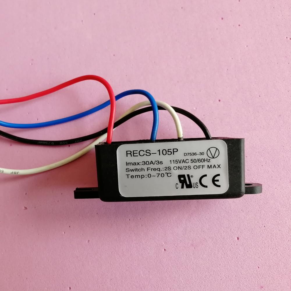
- RECS-105P: Suitable for motors 0-600W, maximum current 30A/3S.
- RECS-120P: Suitable for motors 600-2000W, maximum current 60A/3S.
- RECS-140P: Suitable for motors 2000-4300W, maximum current 120A/3S.
All models operate at 110VAC 50/60Hz and are designed for a switch frequency of 2 seconds ON / 2 seconds OFF.

2. Safety Instructions
- Always disconnect power before installation, maintenance, or troubleshooting.
- Installation should be performed by a qualified electrician or technician.
- Ensure the motor's wattage and current draw do not exceed the switch's specifications.
- Do not operate the switch outside its specified temperature range (0-70°C).
- Avoid exposing the device to moisture or corrosive environments.
- Verify all connections are secure to prevent electrical hazards.
3. Setup and Installation
3.1 Mounting
The RECS series switches are designed for PCB mounting. Ensure a stable and secure mounting location that allows for adequate ventilation and is within the specified operating temperature range.
3.2 Wiring Connections
The switch features a 2-pin connector and screw terminals for electrical connections. Carefully follow the wiring diagram provided with your motor or system. Typically, the red and blue wires are for power input, and the white and black wires are for motor connection. Ensure all connections are tight and properly insulated.
3.3 Dimensions
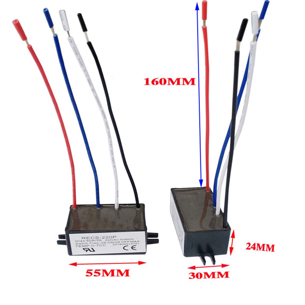
The compact design of the RECS series allows for flexible integration. Refer to the image below for general dimensions. Note that the image displays a RECS-220P model, but the dimensions are illustrative of the series' compact size.
4. Operating Instructions
The RECS electronic centrifugal switch operates automatically. Once properly installed and powered, it will manage the starting and running phases of your single-phase motor. The switch frequency is set to 2 seconds ON and 2 seconds OFF, ensuring controlled motor engagement.
Ensure the motor connected is within the wattage and current limits specified for your particular RECS model (RECS-105P, RECS-120P, or RECS-140P) to guarantee optimal performance and longevity of both the switch and the motor.
5. Maintenance
The RECS series switches are designed for durability and require minimal maintenance. However, periodic checks can help ensure continued reliable operation:
- Visual Inspection: Periodically inspect the switch and its wiring for any signs of damage, wear, or loose connections.
- Cleanliness: Keep the switch free from dust, dirt, and debris. Use a dry, soft cloth for cleaning. Do not use liquid cleaners.
- Environmental Conditions: Ensure the operating environment remains within the specified temperature range of 0-70°C and is free from excessive humidity or corrosive substances.
6. Troubleshooting
If you encounter issues with your RECS electronic centrifugal switch, consider the following troubleshooting steps:
- Motor Not Starting:
- Verify that the power supply is connected and active.
- Check all wiring connections for tightness and correct polarity.
- Ensure the motor's wattage is within the specified range for your RECS model.
- Switch Overheating:
- Confirm the motor load does not exceed the switch's maximum current rating.
- Check the ambient temperature to ensure it is within the 0-70°C operating range.
- Ensure adequate ventilation around the switch.
- Irregular Switching Behavior:
- Re-check all wiring for any loose or incorrect connections.
- Ensure the power supply is stable and within the 110VAC 50/60Hz specification.
If problems persist after following these steps, consult a qualified technician.
7. Specifications
| Feature | Specification |
|---|---|
| Brand | Generic |
| Model (Current Product) | RECS-105P |
| Operation Mode | Automatic |
| Operating Voltage | 110 Volts AC |
| Switch Frequency | 2S ON / 2S OFF |
| Max Temperature | 0-70°C |
| Current Rating (RECS-105P) | 30A/3S |
| Suitable Motor (RECS-105P) | 0-600W |
| Current Rating (RECS-120P) | 60A/3S |
| Suitable Motor (RECS-120P) | 600-2000W |
| Current Rating (RECS-140P) | 120A/3S |
| Suitable Motor (RECS-140P) | 2000-4300W |
| Contact Type | Normally Open |
| Connector Type | 2 Pin |
| Terminal | Screw |
| Material | Copper |
| Item Dimensions (L x W x H) | 2.17 x 0.94 x 1.18 inches (55 x 24 x 30mm) |
| Circuit Type | 1-way |
| Mounting Type | PCB Mount |
| Number of Positions | 1 |
| Wattage (RECS-105P) | 600 watts |
| Color | Black |
| International Protection Rating | IP54 |
| Manufacturer | Fuzhou Hengte Co. |
| UPC | 754525842897 |
8. Warranty and Support
Specific warranty information for this product is not provided in the available details. For any support inquiries or further assistance, please contact the retailer or manufacturer directly.