1. Introduction
This manual provides essential information for the safe and effective operation of your Hantek DSO5072P Digital Storage Oscilloscope. The DSO5072P is a 2-channel oscilloscope designed for various electronic measurement tasks, offering a 70MHz bandwidth and a 1GSa/s real-time sample rate. It features a large 7.0-inch WVGA (800x480) color display, a record length of up to 40K, and USB connectivity for data transfer and PC analysis.
This series also includes the DSO5102P (100MHz bandwidth) and DSO5202P (200MHz bandwidth) models, sharing many operational characteristics with the DSO5072P.
2. What's in the Box
Carefully unpack your Hantek DSO5072P oscilloscope and verify that all items listed below are present and in good condition. If any items are missing or damaged, please contact your supplier.
- Hantek DSO5072P Digital Storage Oscilloscope Unit
- Two Oscilloscope Probes
- USB Cable
- Power Cord
- User Manual (this document)
- Software CD (for PC real-time analysis)

Image 2.1: Contents of the Hantek DSO5072P package, including the oscilloscope unit, two probes, USB cable, power cord, and documentation.
3. Initial Setup
- Power Connection: Connect the provided power cord to the AC input on the rear panel of the oscilloscope and then to a suitable AC power outlet. Ensure the voltage matches the oscilloscope's requirements (100-240V AC, 45-440Hz).
- Probe Connection: Connect the oscilloscope probes to the BNC input connectors (CH1 and CH2) on the front panel. Ensure a secure connection by twisting the probe connector clockwise until it locks.
- Probe Compensation: Before taking measurements, compensate the probes to ensure accurate readings. Connect the probe to CH1 and attach the probe tip to the probe compensation test signal output (usually a square wave). Adjust the compensation screw on the probe until a flat-top square wave is displayed on the screen. Repeat for CH2.
- Power On: Press the power button located on the front panel to turn on the oscilloscope.
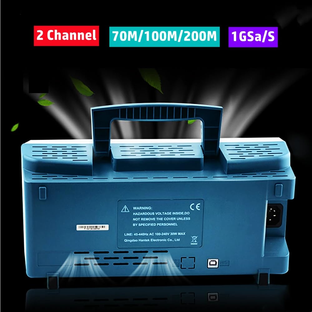
Image 3.1: Rear panel of the Hantek DSO5072P, highlighting the power input and ventilation slots. Note the warning label regarding hazardous voltage.
4. Basic Operation
The Hantek DSO5072P features an intuitive front panel layout with dedicated controls for vertical, horizontal, and trigger settings, along with a clear color display.
4.1 Front Panel Overview

Image 4.1: Front view of the Hantek DSO5072P, showing the 7-inch display, channel inputs, and control knobs/buttons for various functions.
- Vertical Controls: Adjust voltage per division (Volts/Div) and vertical position for each channel (CH1, CH2).
- Horizontal Controls: Adjust time per division (Sec/Div) and horizontal position to control the time base.
- Trigger Controls: Set the trigger level, mode (Edge, Pulse, Video, Slope, Overtime), and source to stabilize waveforms.
- Function Buttons: Access menus for various settings, measurements, and utility functions.
4.2 Acquiring a Waveform
- Connect the probe to the circuit under test.
- Select the desired channel (CH1 or CH2) using the corresponding button.
- Adjust the Volts/Div knob to set the vertical scale appropriate for the signal amplitude.
- Adjust the Sec/Div knob to set the horizontal scale appropriate for the signal frequency.
- Adjust the Trigger Level knob until a stable waveform appears on the display.
- Use the Auto Set button for automatic waveform optimization, if needed.

Image 4.2: The Hantek DSO5072P in operation, demonstrating a user probing a circuit board to acquire a signal.
5. Measurements and Analysis
The DSO5072P offers multiple automatic measurements and mathematical functions to analyze waveforms.
5.1 Automatic Measurements
Press the MEASURE button to access the automatic measurement menu. You can select various parameters such as Peak-to-Peak voltage, RMS voltage, Frequency, Period, Rise Time, Fall Time, and more. The oscilloscope will display these values directly on the screen.
5.2 Math Functions (FFT)
Press the MATH button to access mathematical operations. The oscilloscope supports addition, subtraction, multiplication, division, and Fast Fourier Transform (FFT). FFT allows you to analyze the frequency components of a signal, which is useful for identifying noise or harmonics.

Image 5.1: Examples of waveform displays on the Hantek DSO5072P, illustrating various signal types and the results of automatic measurements and FFT analysis.
6. USB Connectivity and PC Software
The DSO5072P includes USB host and device connectivity, enabling data transfer and remote control.
- USB Host: Connect a USB flash drive to save waveform data, screenshots, or instrument settings.
- USB Device: Connect the oscilloscope to a PC using the provided USB cable. Install the Hantek PC software from the included CD to perform real-time analysis, remote control, and data logging on your computer.
7. Maintenance
Proper maintenance ensures the longevity and accuracy of your oscilloscope.
- Cleaning: Clean the instrument's exterior with a soft, damp cloth. Do not use abrasive cleaners or solvents. Ensure the device is powered off and unplugged before cleaning.
- Storage: Store the oscilloscope in a dry, dust-free environment when not in use.
- Safety: Do not open the instrument casing. Hazardous voltages are present inside. Refer all servicing to qualified personnel. Ensure adequate ventilation during operation.
8. Troubleshooting
If you encounter issues with your Hantek DSO5072P, refer to the following common problems and solutions:
- No Power: Check the power cord connection and the power outlet. Ensure the power button is pressed.
- No Waveform Display: Verify that the probe is correctly connected to both the oscilloscope and the circuit under test. Adjust the Volts/Div and Sec/Div settings. Ensure the trigger level is set appropriately.
- Unstable Waveform: Adjust the trigger level and trigger mode. Check the probe compensation.
- Incorrect Measurements: Ensure probes are properly compensated. Verify the measurement settings.
For persistent issues, consult the full user manual on the software CD or contact Hantek support.
9. Specifications
The following table details the technical specifications for the Hantek DSO5072P, DSO5102P, and DSO5202P models.

Image 9.1: Detailed technical specifications for the Hantek DSO5072P, DSO5102P, and DSO5202P models, covering acquisition, inputs, horizontal, and vertical parameters.
| Category | Description | DSO5202P | DSO5102P | DSO5072P |
|---|---|---|---|---|
| Acquisition | Model | DSO5202P | DSO5102P | DSO5072P |
| Sample Rate | Real-Time Sample: 1GS/s | Real-Time Sample: 1GS/s | Real-Time Sample: 1GS/s | |
| Equivalent Sample | 25GS/s | 25GS/s | 25GS/s | |
| Acquisition Modes | Normal data only | Normal data only | Normal data only | |
| Peak Detect | High-frequency and random glitch capture | High-frequency and random glitch capture | High-frequency and random glitch capture | |
| Average | Waveform Average_selectable 4,8,16,32,64,128 | Waveform Average_selectable 4,8,16,32,64,128 | Waveform Average_selectable 4,8,16,32,64,128 | |
| Inputs | Inputs Coupling | AC, DC, GND | AC, DC, GND | AC, DC, GND |
| Inputs Impedance | 1MΩ±2% ||20pF±3pF | 1MΩ±2% ||20pF±3pF | 1MΩ±2% ||20pF±3pF | |
| Probe Attenuation | 1X, 10X | 1X, 10X | 1X, 10X | |
| Supported Probe Attenuation Factor | 1X, 10X, 100X, 1000X | 1X, 10X, 100X, 1000X | 1X, 10X, 100X, 1000X | |
| Maximum Input Voltage | CAT I and CAT II: 300VRMS (10×), Installation Category; CAT III: 150VRMS (1×). Installation Category II: derate at 20dB/decade above 100kHz to 13V peak AC at 3MHz* and above. For non-sinusoidal waveforms, peak value must be less than 450V. Excursion above 300V should be at less than 100ms duration. RMS signal level including all DC components removed through AC coupling must be limited to 300V. If these values are exceeded, damage to the oscilloscope may occur. | CAT I and CAT II: 300VRMS (10×), Installation Category; CAT III: 150VRMS (1×). Installation Category II: derate at 20dB/decade above 100kHz to 13V peak AC at 3MHz* and above. For non-sinusoidal waveforms, peak value must be less than 450V. Excursion above 300V should be at less than 100ms duration. RMS signal level including all DC components removed through AC coupling must be limited to 300V. If these values are exceeded, damage to the oscilloscope may occur. | CAT I and CAT II: 300VRMS (10×), Installation Category; CAT III: 150VRMS (1×). Installation Category II: derate at 20dB/decade above 100kHz to 13V peak AC at 3MHz* and above. For non-sinusoidal waveforms, peak value must be less than 450V. Excursion above 300V should be at less than 100ms duration. RMS signal level including all DC components removed through AC coupling must be limited to 300V. If these values are exceeded, damage to the oscilloscope may occur. | |
| Horizontal | Sample Rate Range | 500MS/s - 1GS/s | 500MS/s - 1GS/s | 500MS/s - 1GS/s |
| Waveform Interpolation | (sin x)/x | (sin x)/x | (sin x)/x | |
| Record Length | 40K | 40K | 40K | |
| SEC/DIV Range | 2ns/div to 80s/div | 2ns/div to 80s/div | 2ns/div to 80s/div | |
| Sample Rate and Delay Time Accuracy | ±50ppm (at over any ≥1ms time interval) | ±50ppm (at over any ≥1ms time interval) | ±50ppm (at over any ≥1ms time interval) | |
| Offset Range | 2ns/div to 8ns/div; -8div x s/div to 20ms; 20ns/div to 80s/div; -8div x s/div to 40s | 2ns/div to 8ns/div; -8div x s/div to 20ms; 20ns/div to 80s/div; -8div x s/div to 40s | 2ns/div to 8ns/div; -8div x s/div to 20ms; 20ns/div to 80s/div; -8div x s/div to 40s | |
| Delay Time Measurement Accuracy (Full Bandwidth) | Single-shot, Normal mode: ± (1 sample interval + 100ppm × reading + 0.6ns); >16 averages: ± (1 sample interval + 100ppm × reading + 0.4ns); Sample interval = s/div ÷ 200 | Single-shot, Normal mode: ± (1 sample interval + 100ppm × reading + 0.6ns); >16 averages: ± (1 sample interval + 100ppm × reading + 0.4ns); Sample interval = s/div ÷ 200 | Single-shot, Normal mode: ± (1 sample interval + 100ppm × reading + 0.6ns); >16 averages: ± (1 sample interval + 100ppm × reading + 0.4ns); Sample interval = s/div ÷ 200 | |
| Vertical | Vertical Resolution | 8-bit resolution, all channel sampled simultaneously | 8-bit resolution, all channel sampled simultaneously | 8-bit resolution, all channel sampled simultaneously |
| Position Range | 2mV/div to 20V/div: ±400mV; 50mV/div to 20V/div: ±2V; 500mV/div to 2V/div: ±40V; 5V/div to 10V/div: ±50V | 2mV/div to 20V/div: ±400mV; 50mV/div to 20V/div: ±2V; 500mV/div to 2V/div: ±40V; 5V/div to 10V/div: ±50V | 2mV/div to 20V/div: ±400mV; 50mV/div to 20V/div: ±2V; 500mV/div to 2V/div: ±40V; 5V/div to 10V/div: ±50V | |
| Bandwidth | 200MHz | 100MHz | 70MHz | |
| Rise Time at BNC (typical) | 1.8ns | 3.5ns | 5ns | |
| Math | +, -, ×, /, FFT | +, -, ×, /, FFT | +, -, ×, /, FFT | |
| FFT | Windows: Hanning, Flatop, Rectangular, Bartlett, Blackman; 1024 sample point | Windows: Hanning, Flatop, Rectangular, Bartlett, Blackman; 1024 sample point | Windows: Hanning, Flatop, Rectangular, Bartlett, Blackman; 1024 sample point | |
| Bandwidth Limit | 20MHz | 20MHz | 20MHz | |
| Low Frequency Response (-3db) | ≤10Hz at BNC | ≤10Hz at BNC | ≤10Hz at BNC | |
| DC Gain Accuracy | ±3% for Normal or Average acquisition mode. 10V/div to 10mV/div; ±4% for Normal or Average acquisition mode. 5mV/div to 2mV/div | ±3% for Normal or Average acquisition mode. 10V/div to 10mV/div; ±4% for Normal or Average acquisition mode. 5mV/div to 2mV/div | ±3% for Normal or Average acquisition mode. 10V/div to 10mV/div; ±4% for Normal or Average acquisition mode. 5mV/div to 2mV/div | |
| DC Measurement Accuracy | When vertical displacement is zero, and N ≥16: ± (3% × reading + 0.1div + 1mV) only 10mV/div or greater is selected. | When vertical displacement is zero, and N ≥16: ± (3% × reading + 0.1div + 1mV) only 10mV/div or greater is selected. | When vertical displacement is zero, and N ≥16: ± (3% × reading + 0.1div + 1mV) only 10mV/div or greater is selected. |
10. Warranty and Support
Hantek products are designed for reliability and performance. For specific warranty terms and conditions, please refer to the warranty card included with your product or visit the official Hantek website. For technical support, troubleshooting assistance, or service inquiries, please contact Hantek customer service through their official channels.


