1. Introduction
The Hantek DSO3104A is a versatile 4-channel digital oscilloscope integrated with a 16-channel logic analyzer and a 1-channel function/arbitrary waveform generator. Designed for portability and high performance, it offers a 1GSa/s real-time sampling rate and 250MHz bandwidth, making it suitable for various electronic testing and measurement applications. This manual provides essential information for the proper setup, operation, and maintenance of your device.
2. Safety Information
Please read and understand all safety instructions before operating the device to prevent injury or damage to the instrument. Keep this manual for future reference.
- Power Supply: Use only the specified power adapter (12-36V DC). Ensure the power source is stable and correctly rated.
- Environment: Operate the device in a dry, well-ventilated area. Avoid exposure to extreme temperatures, humidity, dust, or corrosive gases.
- Probes: Use only probes rated for the voltage and current being measured. Ensure probes are properly connected before applying power.
- Grounding: Always ensure the device is properly grounded when connected to a power source or other equipment.
- Maintenance: Do not attempt to service the device yourself. Refer all servicing to qualified personnel.
3. Package Contents
Verify that all items are present in the package:
- Hantek DSO3104A Digital Oscilloscope Unit
- USB Cable
- Power Adapter
- Oscilloscope Probes (quantity may vary)
- Logic Analyzer Cables (if applicable)
- Software CD or Download Link
- User Manual (this document)
4. Product Overview
4.1. Front/Top View

This image displays the top view of the Hantek DSO3104A Digital Oscilloscope. The device features a robust anodized aluminum casing with protective rubber bumpers on the corners. The Hantek logo is prominently displayed on the top surface. Ventilation slots are visible along the sides for heat dissipation.
4.2. Input/Output Panel (Left Side)
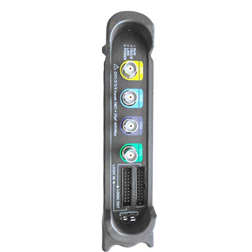
This image shows the left side panel of the DSO3104A, which houses the primary input and output connectors. From top to bottom, these include: four BNC connectors for analog oscilloscope channels (CH1, CH2, CH3, CH4), clearly labeled with color-coded rings. Below these are two multi-pin connectors for Logic In and Logic Out, used for the 16-channel logic analyzer functionality. A warning label indicates input impedance and maximum voltage for channels 1-4.
4.3. Connectivity Panel (Right Side)
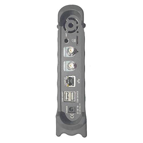
This image illustrates the right side panel of the DSO3104A, featuring various connectivity ports. From top to bottom, these include: an antenna connector (ANT), a BNC output for the function/arbitrary waveform generator (OUTPUT), another BNC connector (likely for external trigger or reference), a LAN/PoE port for network connectivity and optional power over Ethernet, a USB HOST port, a USB DEVICE port for PC connection, a DC power input jack, and a power switch. A cooling fan vent is also visible at the top.
5. Setup
Follow these steps to set up your Hantek DSO3104A:
- Software Installation: Before connecting the device, install the Hantek oscilloscope software on your computer. The software supports Windows 7, Windows 8, and Windows 10. Refer to the provided software CD or download instructions.
- Power Connection: Connect the provided power adapter to the DC power input jack on the right side panel of the oscilloscope. Plug the adapter into a suitable power outlet.
- USB Connection: Connect the oscilloscope to your computer using the supplied USB cable. Use the USB DEVICE port on the oscilloscope and a free USB port on your computer.
- Power On: Flip the power switch on the right side panel to the 'ON' position. The device should power on, and your computer should detect it.
- Probe Connection: Connect the oscilloscope probes to the desired BNC input channels (CH1-CH4) on the left side panel. Ensure a secure connection.
- Logic Analyzer Connection (Optional): If using the logic analyzer, connect the logic analyzer cables to the 'LOGIC IN' and 'LOGIC OUT' ports and to your target circuit.
- Network Connection (Optional): For network control or PoE functionality, connect an Ethernet cable to the LAN/PoE port.
5.1. Multi-Device Connection Example

This diagram illustrates a network setup where multiple Hantek oscilloscopes can be connected to a single computer. The oscilloscopes are connected to a PoE switch, which provides both data and power. The PoE switch then connects to the computer, allowing for centralized control and data acquisition from multiple devices. Fiber-optic communication is also shown as an option for extended distances.
6. Operating Instructions
Once the software is installed and the device is connected, launch the Hantek application on your computer. The software interface is designed to be similar to a traditional benchtop oscilloscope, providing intuitive control over the device's functions.
6.1. Oscilloscope Functions
- Channel Selection: Enable or disable the 4 analog channels (CH1-CH4) as needed.
- Vertical Controls: Adjust voltage per division (V/DIV) and coupling (AC/DC/GND) for each channel. The device offers 1mV-10V/DIV sensitivity.
- Horizontal Controls: Adjust time base (s/DIV) to control the sweep speed.
- Triggering: Configure trigger source (CH1-CH4, EXT), mode (Edge, Pulse, Video, Slope, Timeout), and level to stabilize waveforms.
- Measurements: Utilize over 20 automatic measurement functions (Vpp, Vmax, Vmin, Vavg, RMS, Frequency, Period, Rise Time, Fall Time, etc.) and dynamic cursor tracking.
- Waveform Display: Options include waveform averaging, afterglow, lightness control, reverse, and mathematical operations (add, subtract, multiply, divide, X-Y display).
- FFT Spectrum Analyzer: Perform frequency domain analysis using the built-in FFT function.
- PASS/FAIL Test: Set up criteria for automated waveform comparison against defined masks.
- Recording: Continuous waveform recording and replay function with 200Hz recording bandwidth.
6.2. Logic Analyzer Functions
The integrated 16-channel logic analyzer allows for digital signal analysis. Connect your digital signals to the 'LOGIC IN' port and configure the software for threshold levels and trigger conditions to capture and analyze digital waveforms.
6.3. Function/Arbitrary Waveform Generator
The 1-channel function/arbitrary waveform generator (OUTPUT port) can produce various standard waveforms and user-defined arbitrary waveforms. With a 200MSa/s DDS and 12-bit vertical resolution, it is useful for testing circuits with specific input signals.
7. Software Installation and Usage
The Hantek DSO3104A operates in conjunction with dedicated PC software. The software is compatible with Windows 7, Windows 8, and Windows 10 operating systems.
- Installation: Insert the provided software CD or download the latest version from the official Hantek website. Follow the on-screen instructions to complete the installation.
- Driver Installation: During software installation, ensure that the necessary USB drivers for the oscilloscope are also installed.
- Data Export: Waveform data can be exported to various formats such as EXCEL, BMP, and JPG for further analysis or documentation.
- SCPI Protocol: The device supports SCPI protocol, allowing for programmatic control and integration into automated test systems.
8. Maintenance
Proper maintenance ensures the longevity and accuracy of your DSO3104A.
- Cleaning: Use a soft, dry cloth to clean the exterior of the device. For stubborn dirt, a slightly damp cloth with mild detergent can be used, ensuring no liquid enters the device.
- Storage: When not in use, store the oscilloscope in a clean, dry environment, away from direct sunlight and extreme temperatures.
- Probe Calibration: Periodically check and calibrate your oscilloscope probes according to their respective manuals to ensure accurate measurements.
- Software Updates: Regularly check the Hantek website for software and firmware updates to ensure optimal performance and access to new features.
9. Troubleshooting
If you encounter issues with your DSO3104A, refer to the following common troubleshooting steps:
- Device Not Detected:
- Ensure the USB cable is securely connected to both the oscilloscope (USB DEVICE port) and the computer.
- Verify that the oscilloscope is powered on.
- Check if the USB drivers are correctly installed. Reinstall the software if necessary.
- Try a different USB port on your computer or a different USB cable.
- No Waveform Display:
- Ensure probes are correctly connected to the input channels and the circuit under test.
- Check the vertical (V/DIV) and horizontal (s/DIV) settings in the software; they might be set too high or too low for the signal.
- Adjust the trigger level and mode to ensure a stable trigger.
- Verify that the input signal is within the device's specifications.
- Software Crashing/Freezing:
- Ensure your operating system is up to date.
- Close other demanding applications running on your computer.
- Reinstall the Hantek software.
- Inaccurate Measurements:
- Perform probe compensation if applicable.
- Ensure the probes are correctly attenuated (e.g., 1X, 10X) and the software settings match.
- Check for external interference or noise in the measurement environment.
10. Specifications
The following table provides detailed technical specifications for the Hantek DSO3104A. For a comprehensive comparison across the DSO3000 series, refer to the image below.
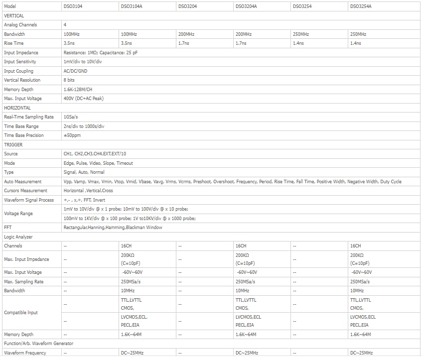
This image presents a detailed comparison table of specifications for various models within the Hantek DSO3000 series, including DSO3104, DSO3104A, DSO3204, DSO3204A, DSO3254, and DSO3254A. Key parameters listed include Analog Channels, Bandwidth, Rise Time, Input Impedance, Input Sensitivity, Vertical Resolution, Input Coupling, Max. Input Voltage, Real-Time Sampling Rate, Time Base Range, Trigger functions, Measurement functions, Waveform Signal Process, Logic Analyzer channels, and Function/Arb. Waveform Generator capabilities. The DSO3104A model is highlighted with 4 analog channels, 100MHz bandwidth, 3.5ns rise time, 1GSa/s sampling rate, and 16 logic analyzer channels.
| Feature | Specification |
|---|---|
| Manufacturer | Hantek |
| Model Number | Q-DSO3104A |
| Item Weight | 1.5 kg |
| Product Dimensions | 16.5 x 3.5 x 19.5 cm |
| Color | Black |
| Material | Acrylonitrile Butadiene Styrene (ABS) |
| Wattage | 1 watts |
| Measurement System | Metric |
| Measurement Accuracy | 0.3% |
| Certifications | CE, ISO 9001, RoHS |
| Country of Origin | China |
11. Warranty and Support
For warranty information and technical support, please refer to the documentation provided with your purchase or visit the official Hantek website. Keep your purchase receipt as proof of purchase for warranty claims.
Hantek provides support for software updates and technical inquiries. Contact their customer service for assistance with any operational issues or product defects.