Introduction
This manual provides comprehensive instructions for the installation, operation, and maintenance of your Fuel Saving HHO DC 4000 CAR system. Please read this manual thoroughly before installation and use to ensure proper function and safety. This product is designed and produced by HHO Plus in the European Union, adhering to technical standards and industrial manufacturing processes.
Product Components
The Fuel Saving HHO DC 4000 CAR kit includes the following main components:
- HHO Gas Generator - Dry Cell: Features 43 plates made of 316L stainless steel.
- Watertank: 1-liter volume with easy level check and refilling opening.
- Control Relay: 30A-12V DC.
- Electrical Cable: HO7V K, 6 mm section, red and black.
- Fuse Holder and Fuse: 30A.
- Safety Nylon Check-Valve.
- Bubbler Tank: For cleaner gas and enhanced system safety.
- Insulated Terminals and Accessories: For all electrical connections.
- High Pressure Hose: For HHO gas.
- Cristal PVC Hose: For the electrolyte.
- Connectors and Sockets: All necessary connections.
- Electrolyte: Potassium hydroxide (KOH).
- Extender for Lambda Sensor: For electronic fuel injection systems.
Setup and Installation
Proper installation is crucial for the performance and safety of the HHO system. Refer to the provided diagrams for electrical and system schematics.
1. Electrical Connections
Connect the HHO system to your vehicle's electrical system as shown in the diagram. Ensure all connections are secure and insulated.

Figure 1: HHO System Electrical Diagram. This diagram illustrates the electrical connections for the HHO system, including the DC battery, fuse, relay switch, and HHO Dry-Cell. Proper grounding is essential.
- Connect the positive (+) terminal of the HHO Dry Cell to the control relay.
- Connect the control relay to the vehicle's ignition source (e.g., ignition switch).
- Install the 30A fuse between the DC battery and the relay for circuit protection.
- Ensure all ground connections are properly secured to the vehicle chassis.
- The standard electrical connections of the cell are: + 5N - 5N + 5N - 5N + 5N - 5N + 5N - (where 5N represents 5 neutral plates).
2. System Plumbing and Component Placement
Install the HHO Dry Cell, Watertank, and Bubbler Tank in suitable locations within the engine bay, ensuring they are secure and away from excessive heat or moving parts.

Figure 2: HHO System Schematics Diagram. This diagram shows the flow of HHO gas from the Dry-Cell through the HHO Tank and into the engine's air intake manifold. Water is returned from the tank to the Dry-Cell.
- Mount the HHO Dry Cell (dimensions: 110x110x220 mm) securely.
- Position the 1-liter Watertank for easy access for level checks and refilling.
- Connect the High Pressure Hose from the HHO Dry Cell to the Bubbler Tank.
- Connect the Bubbler Tank to the vehicle's air intake manifold using appropriate fittings.
- Use the Cristal PVC Hose for electrolyte circulation between the Watertank and the Dry Cell.
- Install the safety nylon check-valve in the HHO gas line to prevent backflow.
- If applicable, install the lambda sensor extender for electronic fuel injection systems.
3. Initial Electrolyte Filling
Prepare the Potassium hydroxide (KOH) electrolyte solution according to the instructions provided in the e-book manual. Carefully fill the Watertank to the indicated level.

Figure 3: HHO Tank. This image shows the HHO Tank, which holds the electrolyte solution and allows for easy level checking and refilling.
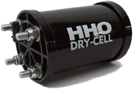
Figure 4: HHO Dry Cell. The main component of the system, responsible for producing HHO gas. This view shows the electrical connection points.

Figure 5: HHO Dry Cell Bottom View. A view of the base of the HHO Dry Cell, showing the mounting points and internal structure.

Figure 6: HHO Bubbler. This component ensures cleaner gas delivery and adds a layer of safety to the system.
Operating Instructions
Once installed, the HHO system operates automatically with the vehicle's ignition. The system is designed for optimal operation current of 25 - 28 Amps and produces approximately 4.0 liters of hydrogen per minute at 50 Amps.
- Ensure the electrolyte level in the Watertank is always above the minimum mark.
- The system will activate when the vehicle's ignition is turned on and deactivate when turned off.
- Monitor the system for any unusual noises or smells during operation.
Maintenance
Regular maintenance ensures the longevity and efficiency of your HHO system.
- Electrolyte Level Check: Periodically check the electrolyte level in the Watertank and refill with distilled water as needed. Do not use tap water.
- Electrolyte Replacement: Replace the electrolyte solution as recommended in the detailed e-book manual, typically every few months depending on usage.
- System Inspection: Regularly inspect all hoses, connections, and electrical wiring for signs of wear, leaks, or corrosion.
- Cleaning: Keep the exterior of the HHO Dry Cell and other components clean to ensure proper heat dissipation.
Troubleshooting
This section provides solutions to common issues you might encounter with your HHO system.
| Problem | Possible Cause | Solution |
|---|---|---|
| No HHO gas production | Low electrolyte level, electrical connection issue, blown fuse. | Check and refill electrolyte. Inspect all electrical connections. Check and replace 30A fuse if blown. |
| System overheating | Incorrect electrolyte concentration, insufficient ventilation. | Verify electrolyte concentration. Ensure adequate airflow around the Dry Cell. |
| Reduced fuel efficiency | System not operating optimally, air leaks in HHO lines. | Check for proper HHO gas flow. Inspect all hoses and connections for leaks. |
For more detailed troubleshooting, refer to the comprehensive installation manual (e-book) provided with your purchase.
Specifications
| Feature | Detail |
|---|---|
| Model Number | HHOPLUS-X100 (Part Number: DC 4000) |
| Generator Type | Dry Cell |
| Dimensions (Dry Cell) | 110x110x220 mm |
| Plates | 43 (316L stainless steel) |
| Voltage | 12/24V |
| Optimum Operation Current | 25 - 28 Amps |
| Hydrogen Production | 4.0 liters per minute (at 50A) |
| Wattage | 4000 watts (Starting Wattage: 4E+3 Watts) |
| Output Wattage | 6 Kilowatts |
| Tank Volume | 1 Liter (Watertank) |
| Recommended Engine Displacement | Up to 6000 cm3 |
| Item Weight | 4.91 Kilograms (approx. 10.8 pounds) |
| Country of Origin | Portugal |
| UPC | 670541159422 |
Warranty and Support
This product is manufactured by HHOPLUS. For specific warranty information and technical support, please refer to the detailed installation manual (e-book) provided at the time of purchase or contact HHOPLUS directly. The installation manual is available in English, French, German, Italian, and Spanish.
For additional assistance, you may contact the seller, HHOPLUS (Seller ID: ATXWK1H067JF2), through the Amazon platform.


