1. Introduction
This manual provides comprehensive instructions for the installation, operation, and maintenance of the Dieffematic CR10MS Photocell Sensor Pair. These sensors are designed to enhance the safety and functionality of automatic gate systems, specifically when paired with Dieffematic Speedy gate amplifiers FOTO9S1A and FOTO9S2A.
The CR10MS photocell sensor pair acts as a safety device, detecting obstacles in the path of an automatic gate to prevent accidents and damage. Proper installation and regular maintenance are crucial for optimal performance and safety.
2. Safety Information
Important: Read all instructions carefully before installation and operation. Failure to follow these instructions may result in serious injury or damage to property.
- Installation should only be performed by qualified personnel in accordance with local electrical and safety regulations.
- Disconnect power to the gate amplifier before performing any installation, maintenance, or troubleshooting.
- Ensure all wiring connections are secure and properly insulated.
- Do not modify the photocell sensors or amplifier in any way.
- Regularly test the functionality of the photocell sensors to ensure they are operating correctly.
3. Package Contents
Verify that all components are present and undamaged upon opening the package. If any items are missing or damaged, contact your supplier immediately.
- 1x Dieffematic CR10MS Transmitter Photocell Sensor
- 1x Dieffematic CR10MS Receiver Photocell Sensor
- Mounting hardware (screws, anchors)
- This instruction manual
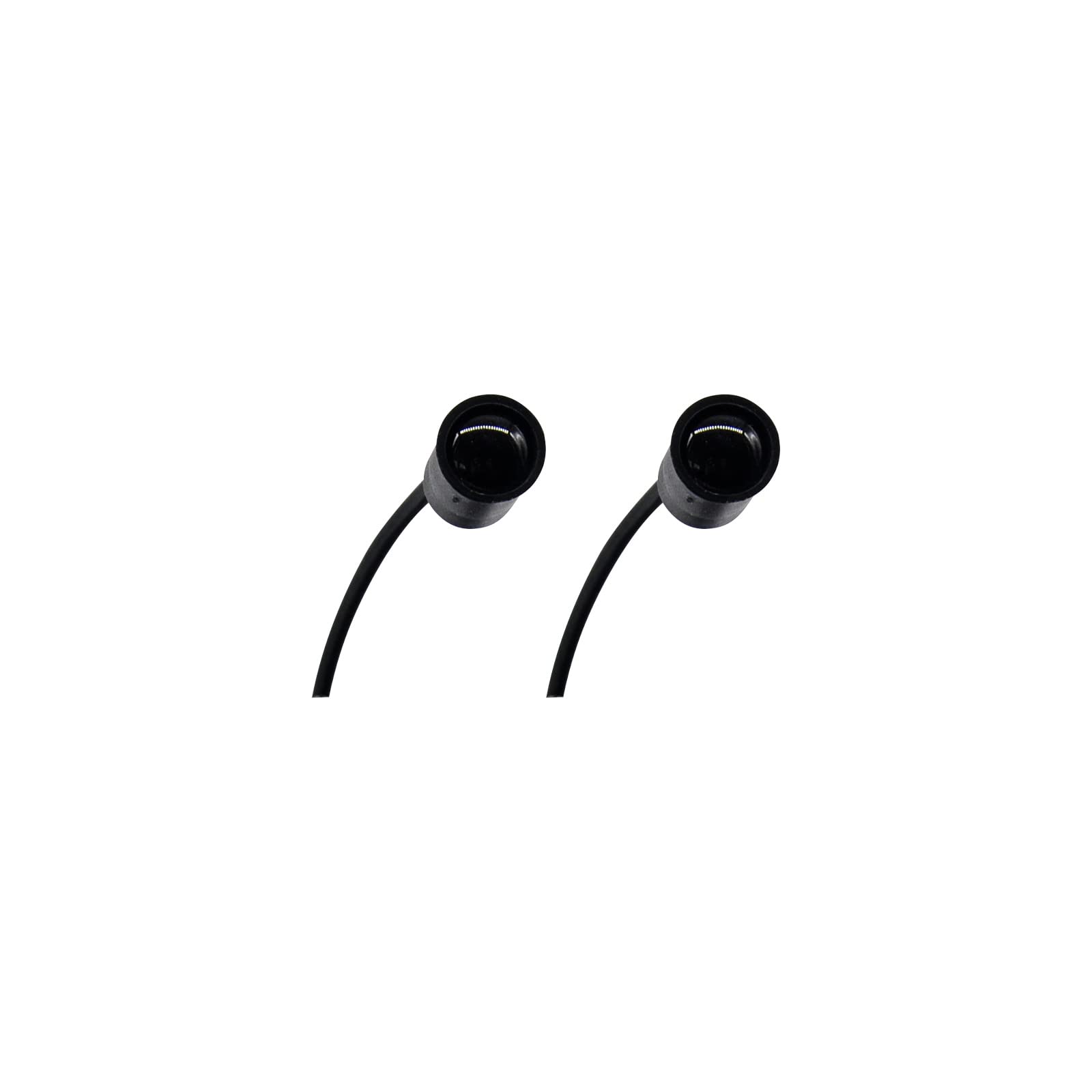
Image 1: The Dieffematic CR10MS Photocell Sensor Pair, showing both the transmitter and receiver units.
4. Setup and Installation
The CR10MS photocell sensors are designed for outdoor use and should be mounted securely on stable surfaces. Ensure the transmitter and receiver are aligned perfectly for optimal performance.
4.1 Mounting Location
- Mount the sensors at a height of approximately 50-60 cm (20-24 inches) from the ground, or as specified by local regulations for gate safety devices.
- Ensure there are no obstructions between the transmitter and receiver.
- Avoid direct sunlight exposure on the receiver lens if possible, as this can interfere with operation.
4.2 Wiring Connections
Refer to the wiring diagram provided with your Dieffematic Speedy gate amplifier (FOTO9S1A / FOTO9S2A) for specific connection points. The CR10MS sensors typically require a 12-24V AC/DC power supply and signal connections to the amplifier.
- Transmitter Unit: Connect power supply wires (typically 12-24V AC/DC). This unit emits the infrared beam.
- Receiver Unit: Connect power supply wires (typically 12-24V AC/DC) and signal output wires to the amplifier's safety input terminals. This unit detects the infrared beam.
(An image showing a typical wiring diagram for the CR10MS sensors connected to a Dieffematic amplifier would be placed here if available.)
Description: A detailed wiring diagram illustrating the connection points for the CR10MS transmitter and receiver units to a Dieffematic FOTO9S1A or FOTO9S2A gate amplifier, showing power and signal lines.
4.3 Alignment
After mounting and wiring, align the transmitter and receiver units. Most units have an indicator LED that illuminates or changes color when proper alignment is achieved. Adjust the angle of each sensor until the indicator shows a strong signal.
(An image demonstrating the alignment process with an indicator LED would be placed here if available.)
Description: An image depicting the alignment process of the photocell sensors, highlighting the indicator LED on the receiver unit that confirms correct alignment with the transmitter.
5. Operating Instructions
Once installed and aligned, the Dieffematic CR10MS photocell sensor pair operates automatically in conjunction with your gate amplifier.
- When the infrared beam between the transmitter and receiver is unobstructed, the gate system will operate normally.
- If an object or person breaks the infrared beam while the gate is closing, the gate will stop and typically reverse its direction to prevent impact.
- If an object or person breaks the infrared beam while the gate is opening, the gate may stop or continue opening, depending on the amplifier's programming.
It is recommended to perform a functional test after installation and periodically thereafter to ensure the sensors are working correctly.
6. Maintenance
Regular maintenance ensures the longevity and reliable operation of your CR10MS photocell sensors.
- Cleaning: Periodically clean the lenses of both the transmitter and receiver units with a soft, damp cloth. Dust, dirt, spiderwebs, or debris can obstruct the infrared beam and cause false detections.
- Inspection: Check for any physical damage to the sensor housings or wiring. Ensure mounting screws are tight and the sensors remain securely in place.
- Functionality Test: At least once a month, test the sensors by placing an object (e.g., a box or your hand) in the path of the gate while it is closing. The gate should stop and reverse.
7. Troubleshooting
If your Dieffematic CR10MS photocell sensors are not functioning as expected, consult the following table for common issues and solutions.
| Problem | Possible Cause | Solution |
|---|---|---|
| Gate does not close, or reverses immediately. |
|
|
| Sensors do not respond to obstruction. |
|
|
| Intermittent operation. |
|
|
If the problem persists after attempting these solutions, contact Dieffematic customer support or a qualified technician.
8. Specifications
| Feature | Detail |
|---|---|
| Model | CR10MS |
| Compatibility | Dieffematic Speedy Gate Amplifiers FOTO9S1A / FOTO9S2A |
| Type | Infrared Photocell Sensor Pair (Transmitter & Receiver) |
| Power Supply | 12-24V AC/DC (Typical, refer to amplifier manual) |
| Range | (Specific range not provided, typical for gate sensors is 10-20m) |
| Operating Temperature | (Not provided, typical for outdoor use is -20°C to +55°C) |
| Protection Rating | (Not provided, typical for outdoor use is IP44 or higher) |
Note: Specific technical details such as range, operating temperature, and IP rating were not provided in the product data. Please refer to the product packaging or Dieffematic's official website for complete specifications.
9. Warranty and Support
Dieffematic products are manufactured to high-quality standards and are covered by a manufacturer's warranty against defects in materials and workmanship. The specific warranty period may vary by region and product type.
For warranty claims, technical support, or further assistance, please contact your authorized Dieffematic dealer or visit the official Dieffematic website. Please have your product model (CR10MS) and purchase information ready when contacting support.
Manufacturer: Dieffematic
ASIN: B0C6R2CTNT
Manufacturer Reference: 234939369379