1. Introduction
This manual provides detailed instructions for the Voktta DC 5V-30V Programmable Delay Relay Module, model ZK-KTD2. This versatile module is designed for various timing control applications, offering adjustable delay settings and multiple operating modes. Please read this manual thoroughly before operation to ensure correct usage and optimal performance.
1.1. Key Features
- Wide Voltage Range: DC 5V - 30V, with Micro USB 5.0V power support.
- Adjustable Timing: Continuously adjustable from 0.1 seconds to 999 minutes.
- High Load Capacity: Controls devices up to DC 30V/5A or AC 220V/5A.
- Memory Function: Automatically saves all set parameters (OP, CL, LOP, CLL, CLH) after power off.
- Multi-functionality: Includes emergency stop and reverse polarity protection.
- Sleep Mode: Display turns off after 3 minutes of inactivity, wakes with any button press.
- Passive Relay Output: The relay output is a passive contact, controlling the on/off state of a line without providing current output.
1.2. Applications
The ZK-KTD2 module is suitable for a wide range of applications requiring precise timing control, such as:
- Access control systems
- Water heater control
- Automatic pet feeders (e.g., cat food dispensers)
- Lighting control
- Industrial automation
- DIY projects requiring timed switching
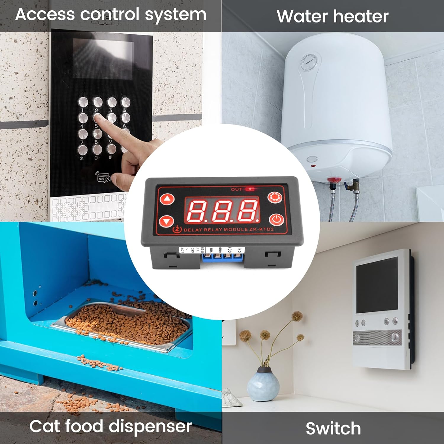
Figure 1: Example applications of the ZK-KTD2 module.
2. Product Overview
2.1. Module Components
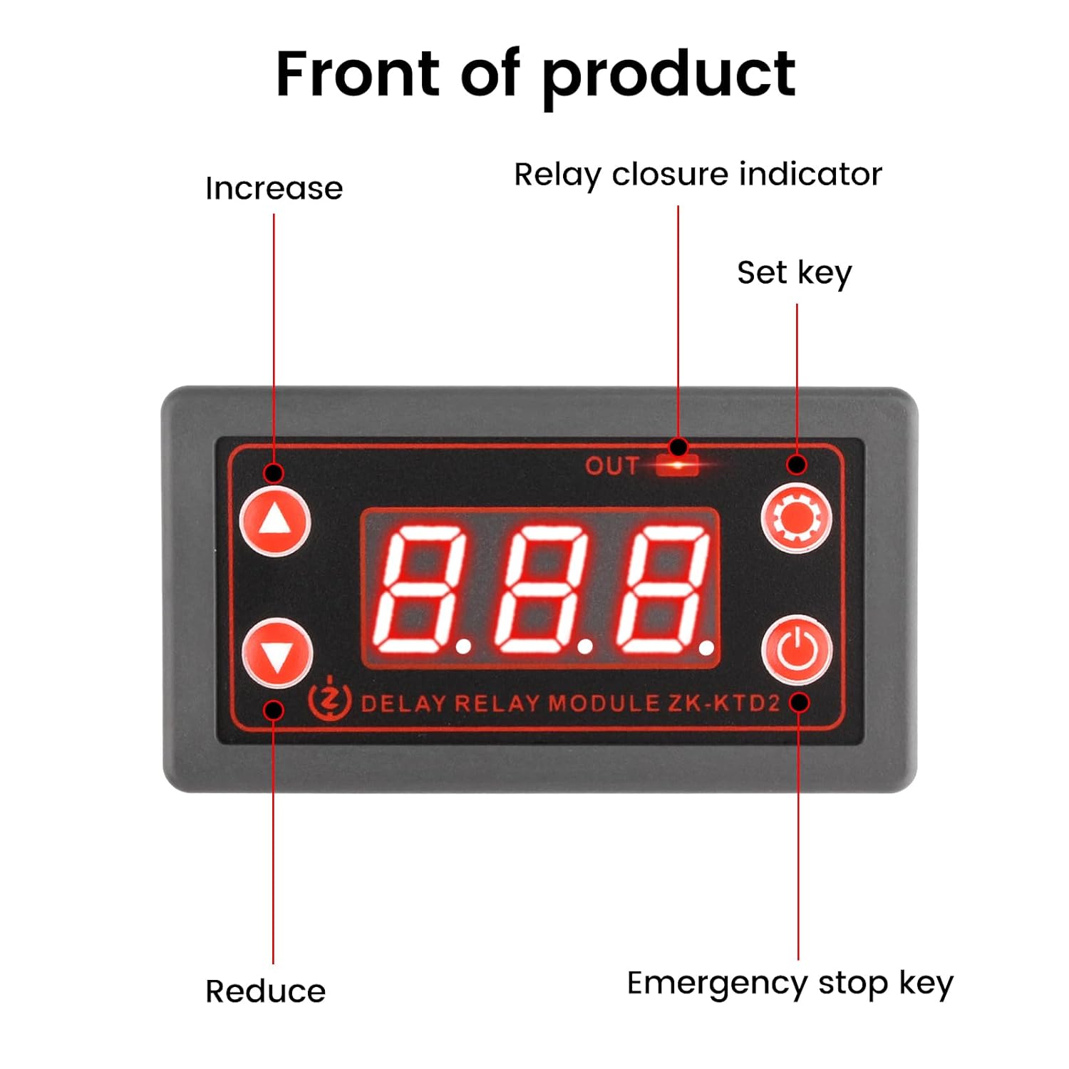
Figure 2: Front view of the ZK-KTD2 module with labeled controls.
- LED Display: Shows current time, mode, and parameter settings.
- OUT Indicator: Illuminates when the relay is active (closed).
- Increase Button (Up Arrow): Used to increase values or navigate menus.
- Reduce Button (Down Arrow): Used to decrease values or navigate menus.
- Set Key (Gear Icon): Enters programming mode and confirms settings.
- Emergency Stop Key (Power Icon): Toggles the relay output on/off immediately.
2.2. Connection Terminals
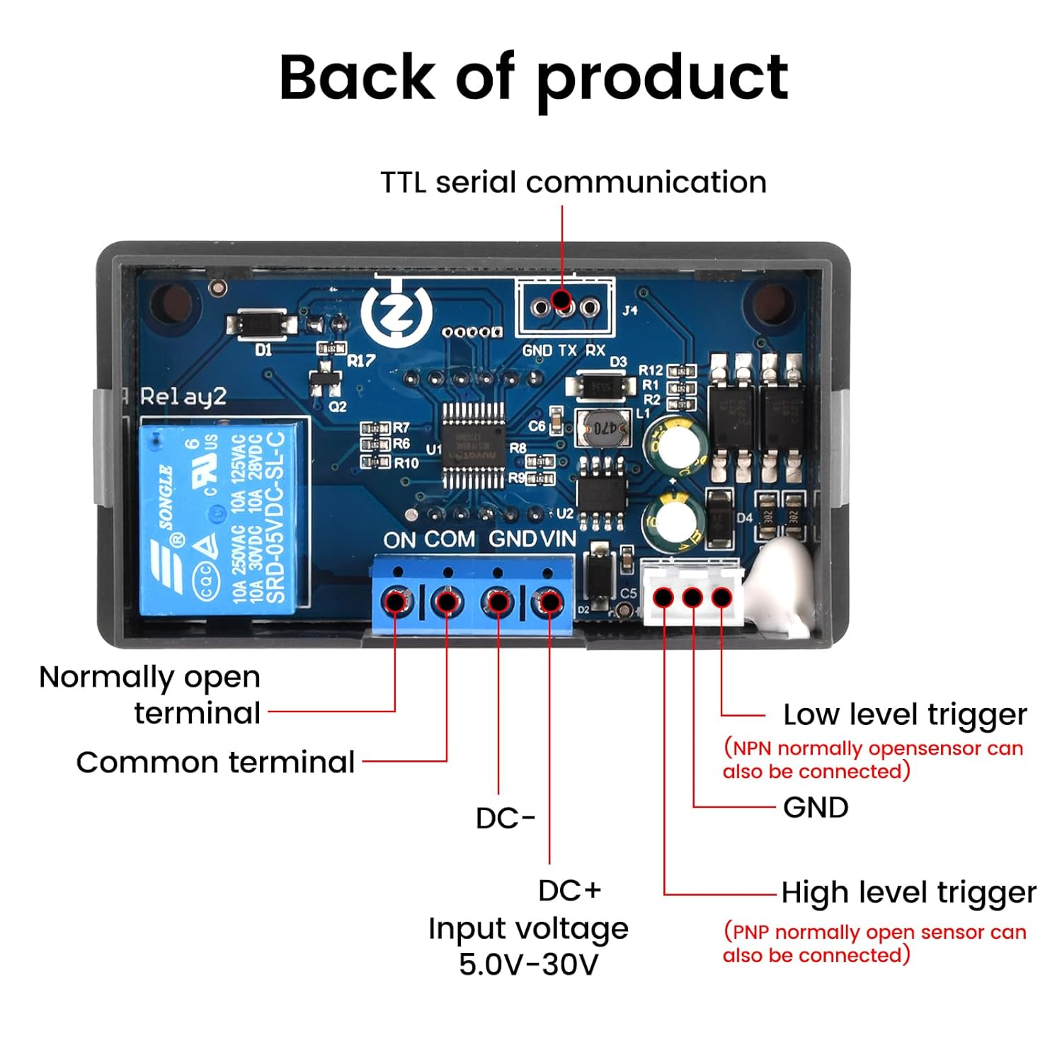
Figure 3: Back view of the ZK-KTD2 module with labeled connection terminals.
- VIN / GND: DC 5.0V-30V power input. Micro USB 5.0V can also be used for power.
- DC+ / DC-: Input voltage terminals (5.0V-30V).
- ON: Normally Open terminal of the relay.
- COM: Common terminal of the relay.
- LOW: Low-level trigger input (NPN normally open sensor can be connected).
- HIGH: High-level trigger input (PNP normally open sensor can be connected).
- GND (Trigger): Ground for trigger inputs.
- TTL Serial Communication (GND TX RX): For advanced control and data communication.
3. Setup and Wiring
3.1. Power Supply Connection
The module can be powered by a DC 5V-30V source connected to the VIN/GND terminals or via a 5.0V Micro USB cable. Ensure the correct polarity when connecting the DC power supply to prevent damage.
3.2. Load Wiring
The relay output is a passive contact (ON, COM). This means it acts as a switch and does not provide power to the load. You must connect your load and its power source through these contacts.
- Identify the power source for your load (e.g., DC 12V, AC 220V).
- Connect one side of your load to the power source.
- Connect the other side of your load to the ON (Normally Open) terminal of the relay.
- Connect the COM (Common) terminal of the relay to the other side of your load's power source (e.g., ground for DC, neutral for AC).
- Ensure all connections are secure and insulated.
Warning: Always disconnect power before making any wiring changes. Incorrect wiring can damage the module or connected devices.
3.3. Trigger Input (Optional)
If using an external trigger, connect it to the LOW or HIGH trigger input terminals and the corresponding GND. The type of sensor (NPN for LOW, PNP for HIGH) determines the appropriate connection.
4. Operating Instructions
4.1. Display Modes
The module has several display modes, indicated by the LED display. The default display shows the current operating mode or time value.
4.2. Parameter Settings (OP, CL, LOP)
The module supports various operating modes, each with specific parameters:
- OP: On-time (relay closes for this duration).
- CL: Off-time (relay opens for this duration).
- LOP: Loop count (number of cycles for cycle mode).
These parameters are independent and automatically saved.
4.3. Entering Programming Mode
- Press and hold the Set Key (gear icon) for 3 seconds to enter programming mode. The display will show the current operating mode (e.g., P1.1).
- Use the Increase and Reduce buttons to select the desired operating mode (P1.1 to P5.x).
- Press the Set Key briefly to enter parameter setting for the selected mode. The first parameter (e.g., OP) will flash.
- Use the Increase and Reduce buttons to adjust the value.
- Press the Set Key briefly to move to the next parameter (e.g., CL, LOP). Repeat adjustment.
- After setting all parameters for the mode, press and hold the Set Key for 3 seconds to save settings and exit programming mode. The module will return to its normal operating state.
4.4. Time Unit Selection
While in parameter setting mode (e.g., OP flashing), briefly press the Emergency Stop Key (power icon) to cycle through time units:
- xxx. (decimal point in the hundreds place): 0.1 seconds to 99.9 seconds
- xx.x (decimal point in the tens place): 1 second to 999 seconds
- x.x.x. (no decimal points): 1 minute to 999 minutes
4.5. Emergency Stop Function
Briefly press the Emergency Stop Key (power icon) during operation to immediately stop or start the relay output. The display will show "OFF" when stopped and "ON" when active.
4.6. Sleep Mode
If no operation is performed for 3 minutes after startup, the display will automatically turn off to save power. Press any button to wake up the display and resume operation.
5. Maintenance
- Keep the module clean and free from dust and moisture.
- Avoid exposing the module to extreme temperatures or direct sunlight.
- Regularly check wiring connections for looseness or corrosion.
- Do not attempt to disassemble or repair the module yourself. Refer to qualified personnel for service.
6. Troubleshooting
| Problem | Possible Cause | Solution |
|---|---|---|
| Module does not power on. | No power supply or incorrect voltage/polarity. | Check power connections (5V-30V DC or Micro USB 5V). Ensure correct polarity. |
| Relay does not switch. | Incorrect wiring of the load, incorrect mode settings, or emergency stop active. | Verify load wiring (ON/COM terminals). Check operating mode and parameter settings. Press Emergency Stop Key to ensure it's not in "OFF" state. |
| Display is off. | Module is in sleep mode. | Press any button to wake up the display. |
| Parameters not saving. | Did not exit programming mode correctly. | Ensure you press and hold the Set Key for 3 seconds to save and exit after setting parameters. |
For further assistance, please refer to the product manual available on the product page or contact Voktta customer support.
7. Specifications

Figure 4: Physical dimensions of the ZK-KTD2 module.
| Feature | Detail |
|---|---|
| Brand | Voktta |
| Model Number | ZK-KTD2 (GXMA0027-001) |
| Input Voltage | DC 5V - 30V (supports Micro USB 5.0V) |
| Timing Range | 0.1 seconds to 999 minutes (continuously adjustable) |
| Load Capacity | DC 30V / 5A or AC 220V / 5A |
| Contact Type | Normally Open (Passive Contact) |
| Contact Material | Copper |
| Operating Mode | Automatic |
| Mounting Type | DIN Rail Mount |
| Product Dimensions (L x W x H) | 7.9 x 4.3 x 2.7 cm (3.11 x 1.69 x 1.06 inches) |
| Weight | 60 grams |
| Country of Origin | China |
8. Warranty and Support
Voktta products are designed for reliability and performance. For any questions, technical support, or warranty claims, please contact Voktta customer service. Refer to your purchase documentation for specific warranty terms and contact information.
You may also find additional resources and product information on the official Voktta product page or website.