SOGTICPS SY10048
SOGTICPS 100A MPPT Solar Charge Controller User Manual
Model: SY10048 | Brand: SOGTICPS
1. Introduction
This manual provides detailed instructions for the installation, operation, and maintenance of your SOGTICPS 100A MPPT Solar Charge Controller, model SY10048. This intelligent regulator is designed to efficiently manage power flow from your solar panels to your battery bank, ensuring optimal charging and system protection.
Key features include advanced MPPT (Maximum Power Point Tracking) technology for high efficiency, automatic recognition of 12V, 24V, 36V, and 48V battery systems, and comprehensive safety protections. It is compatible with various battery types, including Seal, GEL, Flooded, and LifePO4 batteries, and features dual USB 5V charging ports for added convenience.
Note: While incorporating advanced tracking algorithms, this controller combines MPPT and PWM charging technologies to deliver high charging efficiency and value. It may not provide 100% true MPPT functionality as found in some higher-end dedicated MPPT units.
2. Safety Information
Please read all instructions carefully before installation and operation. Failure to follow these instructions may result in serious injury, damage to the controller, or damage to other components in your solar system.
- Ensure all connections are secure and correct before applying power. Incorrect wiring can cause damage.
- Always connect the battery to the controller first, and disconnect the battery last.
- This controller is designed for specific battery voltages (12V/24V/36V/48V). Ensure your battery system matches the controller's auto-recognition capabilities.
- The controller includes multiple protection features:
- Battery over-voltage and over-current protection
- Power failure protection
- Overcharge protection
- Deep discharge protection
- Reverse connection protection
- Overheat temperature protection
- Do not attempt to disassemble or repair the controller yourself. Refer to qualified personnel for service.
- Install the controller in a well-ventilated area, away from flammable materials and direct sunlight.
3. Product Overview
3.1. Controller Appearance

Image: Front view of the SOGTICPS 100A MPPT Solar Charge Controller, showing the LCD display, control buttons, and connection terminals.
3.2. LCD Display Interface
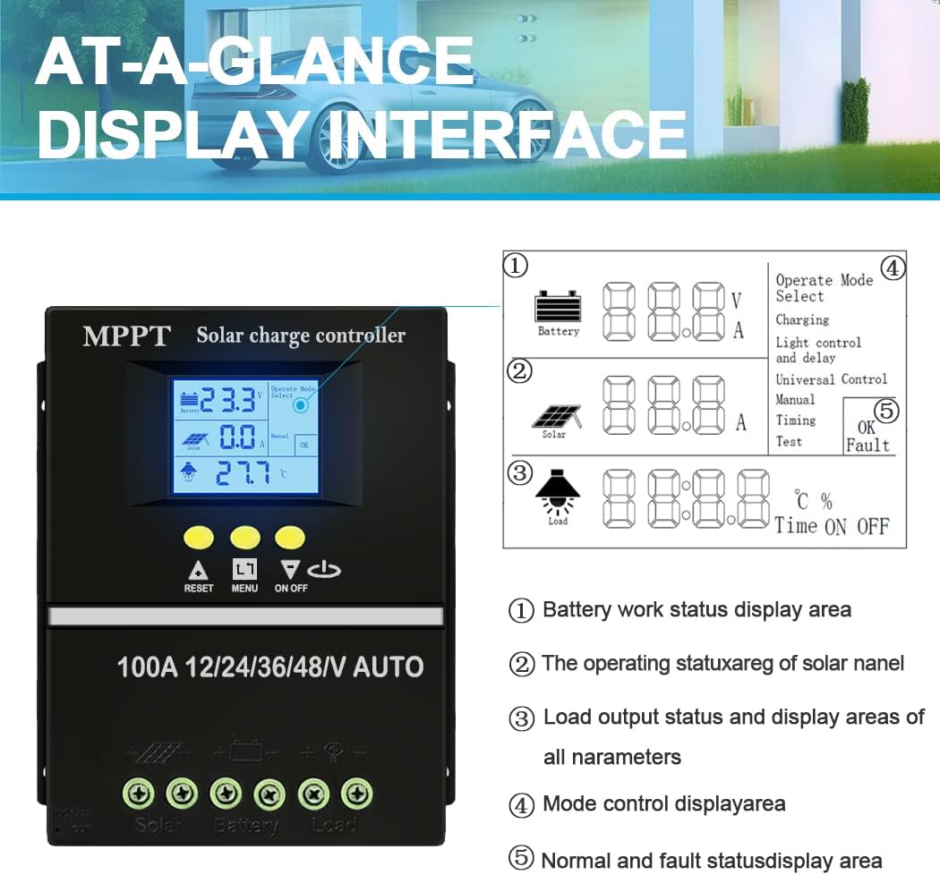
Image: Detailed view of the controller's LCD display with numbered callouts. The display dynamically shows operation data and working status.
- Battery work status display area (Voltage, Amperage)
- Operating status of solar panel (Voltage, Amperage)
- Load output status and display areas of all parameters (e.g., temperature, delay time)
- Mode control display area (Operating Mode Select)
- Normal and fault status display area (OK, Fault)
3.3. Control Buttons
- RESET: Resets the controller.
- MENU: Navigates through display screens and settings.
- UP/DOWN Arrows: Adjusts parameter values or selects options.
- ON/OFF: Controls the load output.
4. Setup and Installation
4.1. Mounting the Controller
Mount the controller vertically on a flat, non-flammable surface in a well-ventilated indoor area. Ensure there is sufficient clearance around the controller for heat dissipation. Avoid direct sunlight, high temperatures, and humid environments.
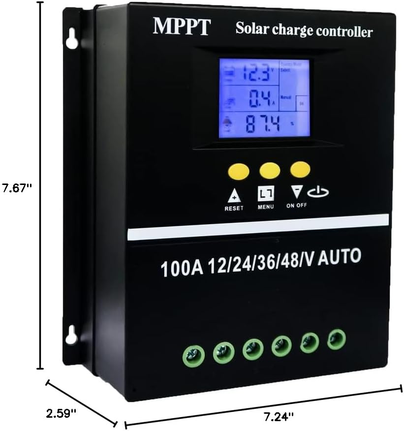
Image: Diagram showing the dimensions of the solar charge controller (7.67"L x 2.59"W x 7.24"H).
4.2. Wiring Sequence
Follow the wiring sequence precisely to prevent damage to the controller or other components. Use appropriate wire gauges for your system's current and distance.
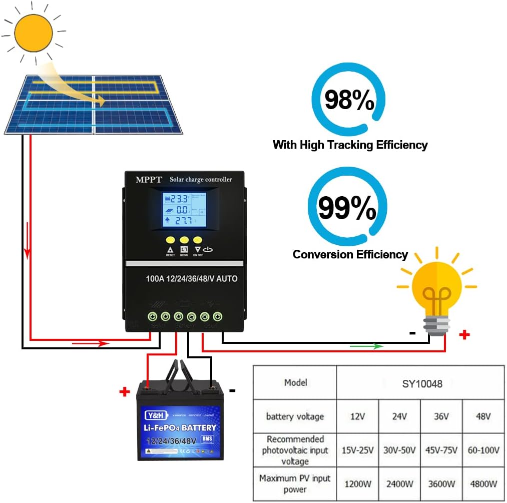
Image: Wiring diagram illustrating the connection order for solar panels, battery, and DC load to the charge controller.
- Connect the Battery: Connect the battery to the controller's battery terminals (positive to positive, negative to negative). The controller will automatically detect the battery voltage (12V/24V/36V/48V). Ensure the battery is fully charged before connecting solar panels.
- Connect the Solar Panels: Connect the solar panel array to the controller's PV terminals (positive to positive, negative to negative). Ensure the solar panel voltage is within the controller's acceptable range (Max 100V Input).
- Connect the DC Load (Optional): Connect your DC loads to the controller's load terminals (positive to positive, negative to negative).
Disconnection Sequence: To disconnect the system, reverse the order: first disconnect the DC load, then the solar panels, and finally the battery.
5. Operating Modes and Charging
5.1. Battery Charging Options

Image: Visual representation of the controller's compatibility with various battery types, including Seal, GEL, Flooded, and LifePO4 batteries.
The controller supports charging for a variety of battery types, including Seal, GEL, Flooded, and LifePO4 batteries. The charging parameters can be adjusted via the LCD interface to match your specific battery requirements.
5.2. Four Charging Stages

Image: Icons representing the four stages of the battery charging algorithm: Bulk Charge, Boost Charge, Float Charge, and Equalization Charge.
The controller employs a rapid, efficient, and safe battery charging algorithm that includes four main stages:
- Bulk Charge: Charges the battery at its maximum current until it reaches a set voltage.
- Boost Charge: Continues charging at a slightly lower current to ensure the battery is fully charged.
- Float Charge: Maintains the battery at a constant voltage, compensating for self-discharge.
- Equalization Charge: Periodically overcharges flooded batteries to balance cell voltages and prevent sulfation. (Not applicable for sealed or gel batteries).
5.3. Load Working Modes
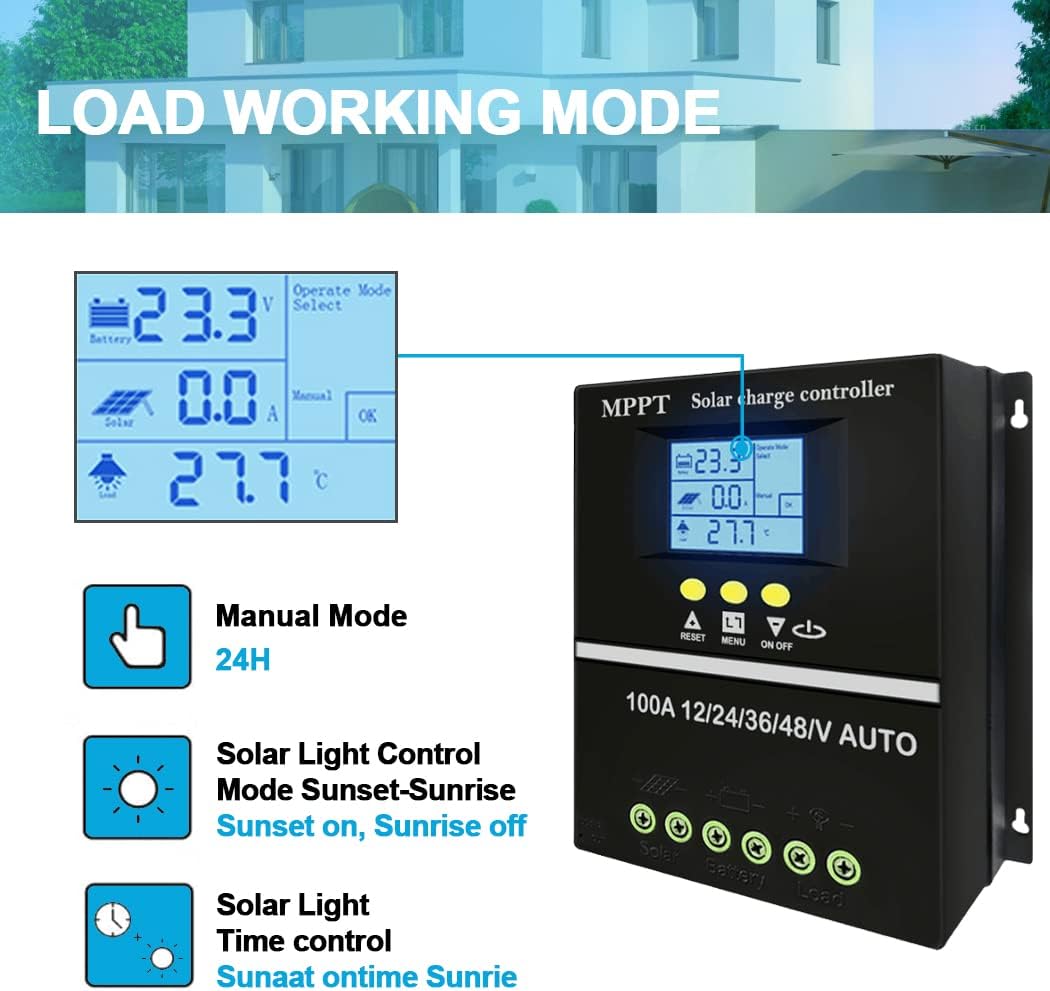
Image: Diagram illustrating the different load working modes available on the controller, including Manual, Solar Light Control, and Solar Light Time Control.
The controller offers 7 operating modes for managing the DC load output:
- Charging Mode: Standard battery charging.
- Light Control Mode: Load turns on at sunset and off at sunrise.
- Light Control + Time Delay Control Mode: Load turns on at sunset and stays on for a set duration.
- Universal Control Mode: Load is always on.
- Manual Control Mode: Load is controlled manually via the ON/OFF button.
- Timing Control Mode: Load turns on and off at specific programmed times.
- Test Mode: For system testing.
Refer to the controller's LCD interface and button functions to select and adjust these modes.
6. Maintenance
Regular maintenance ensures the longevity and optimal performance of your solar charge controller.
- Keep the controller clean and free from dust and debris. Use a dry cloth for cleaning.
- Periodically check all wiring connections to ensure they are tight and free from corrosion.
- Inspect the controller for any signs of physical damage or overheating.
- Ensure proper ventilation around the unit is maintained.
7. Troubleshooting
This section addresses common issues you might encounter with your solar charge controller.
| Problem | Possible Cause | Solution |
|---|---|---|
| LCD display is blank or not lighting up. | No power from battery or incorrect battery connection. |
|
| Battery not charging from solar panels. |
|
|
| Load not turning on. |
|
|
8. Specifications
| Feature | Detail |
|---|---|
| Model | SY10048 |
| Brand | SOGTICPS |
| Current Rating | 100A |
| System Voltage | 12V/24V/36V/48V Auto Recognition |
| Max PV Input Voltage | 100V |
| Display Type | LCD |
| Charging Port Type | Dual USB (5V) |
| Product Dimensions | 7.67 x 2.59 x 7.24 inches |
| Item Weight | 1.85 pounds |
| Color | Black |
| Country of Origin | China |
9. Warranty and Support
SOGTICPS offers a 1-year warranty for this product. We also provide lifetime technical support to assist you with any questions or issues you may encounter.
For technical support or warranty claims, please feel free to contact our customer service team. Our engineers are available to provide advice and solutions.
You can also refer to the official User Guide PDF for more detailed information: Download User Guide (PDF)
Related Documents - SY10048
 |
SY-SLCD Solar Controller Instructions and Specifications Comprehensive instructions for the SY-SLCD solar controller, detailing its functions, operating modes, display indicators, and protection parameters for optimal use with solar power systems. |
 |
DROK 36V Digital Battery Capacity Monitor User Manual This document provides instructions and specifications for the DROK 36V Digital Battery Capacity Monitor. It covers features, installation, programming modes, and technical parameters for monitoring battery status. |
 |
Aideepen DC7-100V Digital Battery Indicator: Specifications and User Guide Detailed information on the Aideepen DC7-100V digital voltmeter and battery capacity tester. Covers product specifications, features, supported battery types (ternary lithium, lithium iron, lead-acid), voltage measurement range, operating current, dimensions, and comprehensive instructions for mode setting and button operation. |
 |
CW12V30A DC-DC Converter Installation and Wiring Guide Installation and wiring instructions for the CSTEOFPW CW12V30A DC-DC Converter, including input/output specifications and connection diagrams. |
 |
YOTTO OVER LAND Combusto Diesel Heater Instruction Manual Comprehensive instruction manual for the YOTTO OVER LAND Combusto Diesel Heater, covering operation, setup, troubleshooting, and safety guidelines for optimal performance and safety. |
Ask a question about this manual
Ask about setup, troubleshooting, compatibility, parts, safety, or missing instructions. Manuals+ will review the question and use this page’s manual context to help answer it.