1. Product Overview
The Y&H 100A Solar Charge Controller is designed to manage power flow from your solar panels to your battery bank, ensuring efficient and safe charging. It features advanced Maximum Power Point Tracking (MPPT) technology for optimal energy harvesting and is compatible with various battery types.
Important Note: This controller utilizes high-quality compatible MPPT + PWM solar regulation. It is not a 100% true MPPT controller, but it offers efficient performance for its class.

Figure 1: Front view of the Y&H 100A Solar Charge Controller, showing the LCD display and control interface.

Figure 2: Side view of the Y&H 100A Solar Charge Controller.
2. Key Features
- Advanced Maximum Power Point Tracking (MPPT) technology with tracking efficiency not less than 99.5%.
- Dynamic LCD screen display for operating data and device status.
- Compatibility with Seal, Gel, Flooded, and LiFePO4 battery types.
- Two 5V USB charging ports for external devices.
- Automatic identification of 12V/24V/36V/48V battery systems.
- Comprehensive protection features: over-voltage, over-current, and over-temperature protection.
- Seven selectable working modes for diverse applications.
- Display of key controller parameters: working mode, battery voltage, PV charging current, battery discharge current, product operating temperature, and delay time.
- User-adjustable and savable controller parameters.
- LCD display with backlight for improved visibility.

Figure 3: The controller supports multiple battery types, including SLD, GEL, Flooded, and Lithium (LiFePO4).
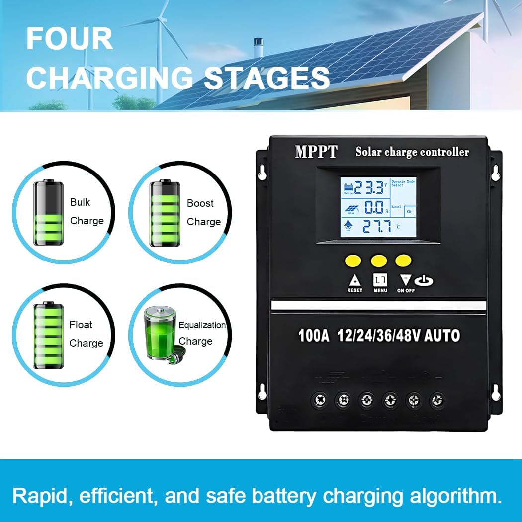
Figure 4: The controller employs a four-stage charging algorithm for efficient and safe battery charging.
3. Safety Instructions
Please read all instructions carefully before installation and operation. Failure to follow these instructions may result in serious injury, damage to the controller, or damage to other components.
- Ensure all connections are tight and correct to avoid loose connections that can cause excessive heat.
- Install the controller in a well-ventilated area, away from flammable materials and direct sunlight.
- Connect the battery first, then the solar panel, and finally the load. Disconnect in the reverse order.
- Do not attempt to repair or modify the controller yourself. Contact qualified personnel for service.
- Use appropriate circuit breakers or fuses for all connections to protect against overcurrent.
- Wear protective eyewear when working with batteries.
4. Installation and Wiring
Proper installation is crucial for the safe and efficient operation of your solar charge controller. Follow these steps carefully:
- Prepare for Installation: Choose a dry, well-ventilated location, protected from direct sunlight and moisture. Ensure there is sufficient space around the controller for heat dissipation.
- Connect the Battery: Connect the battery to the controller's battery terminals. Ensure correct polarity (+ to + and - to -). The controller will automatically detect the battery voltage.
- Connect the Solar Panel: Connect the solar panel to the controller's PV terminals. Again, observe correct polarity.
- Connect the Load (Optional): If you are connecting a DC load directly to the controller, connect it to the load terminals. Ensure correct polarity.

Figure 5: Wiring diagram for the Y&H 100A Solar Charge Controller. Connect battery first, then solar panel, then load.

Figure 6: Rear view of the controller, illustrating the connection terminals and USB ports.
5. Operating the Controller
The controller's LCD display and buttons allow for monitoring and configuration.
5.1 LCD Display Interface
The LCD screen dynamically displays various operating parameters and the device's working status.
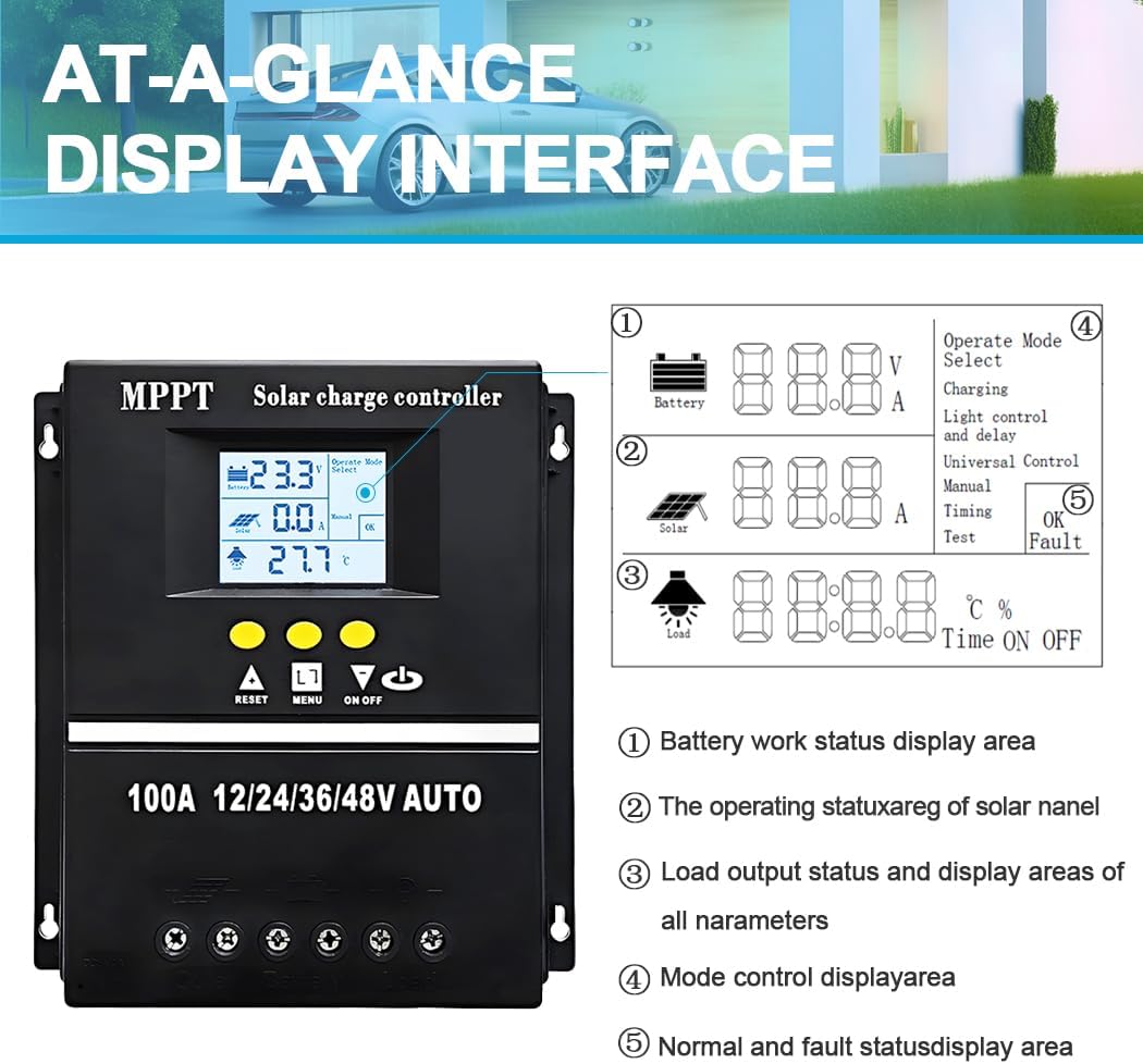
Figure 7: At-a-glance display interface, showing battery work status, solar panel operating status, load output status, mode control, and fault status areas.
5.2 Working Modes
The controller offers seven distinct working modes to suit different application needs:
- Charge Mode: No discharge under any circumstances.
- Light Control Mode: Discharges after a 10-minute delay when night is detected, stops discharge after a 10-minute delay when day is detected.
- Light Control and Delay Mode: Discharges after a 10-minute delay when night is detected, then counts down for a user-set duration (up to 23:59). Discharge stops when the timer reaches zero.
- Universal Control Mode: Continuous discharge under normal conditions.
- Manual Control Mode: Allows manual control of discharge (on/off).
- Time Control Mode: Configurable schedule for opening or closing discharge.
- Test Mode: Similar to Light Control and Delay Mode, but with a fixed 10-minute delay.
The controller also features undervoltage protection. If discharge continues by holding a button for 5 seconds under undervoltage, be aware that this can potentially damage the battery.

Figure 8: Overview of selectable load working modes.
5.3 Parameter Settings
Certain controller parameters, such as battery type, charge/discharge thresholds, and delay times, can be modified, set, and saved by the user via the control buttons and LCD interface. Refer to the on-screen menus for specific adjustment options.
6. Maintenance
Regular maintenance ensures the longevity and optimal performance of your solar charge controller.
- Inspect Connections: Periodically check all wiring connections for tightness and corrosion. Loose connections can lead to power loss and overheating.
- Clean the Controller: Keep the controller clean and free from dust and debris. Use a dry cloth to wipe the exterior. Do not use liquids or solvents.
- Ventilation: Ensure that the ventilation openings are not blocked to allow for proper heat dissipation.
- Battery Health: Monitor your battery's health and voltage regularly. Ensure it is compatible with the controller's settings.
- Environmental Conditions: Verify that the controller is operating within its specified temperature range and protected from extreme weather conditions.
7. Troubleshooting
If you encounter issues with your Y&H 100A Solar Charge Controller, refer to the following common problems and solutions:
| Problem | Possible Cause | Solution |
|---|---|---|
| No display on LCD | Battery not connected or low voltage; reverse polarity. | Check battery connections and voltage. Ensure correct polarity. |
| Battery not charging | Solar panel not connected; low solar input; incorrect battery type setting. | Check solar panel connections and ensure sufficient sunlight. Verify battery type setting. |
| Load not working | Load disconnected; battery low; load mode setting incorrect; overcurrent protection. | Check load connections. Ensure battery has sufficient charge. Adjust load mode. Reduce load. |
| Overheating | Poor ventilation; excessive load. | Ensure adequate airflow around the controller. Reduce load if necessary. |
8. Specifications
Detailed technical specifications for the Y&H 100A Solar Charge Controller:
| Parameter | Value |
|---|---|
| Model Number | 100A (SY10048) |
| Battery Voltage | 12V/24V/36V/48V Auto |
| Charge Current | 100 A |
| Max Solar Input (12V Battery) | 15-25V |
| Max Solar Input (24V Battery) | 30-50V |
| Max Solar Input (36V Battery) | 45-75V |
| Max Solar Input (48V Battery) | 60-100V |
| Max PV Input Power (12V Battery) | 1200 W |
| Max PV Input Power (24V Battery) | 2400 W |
| Max PV Input Power (36V Battery) | 3600 W |
| Max PV Input Power (48V Battery) | 4800 W |
| Dimensions (L x W x H) | 19 x 18 x 6 cm |
| Weight | 890 grams |
| Material | Plastic |
| Display Type | LCD |
| Included Components | MPPT + PWM Controller |

Figure 9: Physical dimensions of the controller.
9. Warranty and Support
For warranty information, technical support, or service inquiries, please contact the manufacturer or your point of purchase. Keep your purchase receipt as proof of purchase.