
1. Introduction
This manual provides essential instructions for the safe and effective operation of the JDSU VIAVI MTS 6000 Optical Time Domain Reflectometer (OTDR) equipped with the E8126B module. The MTS 6000 is a compact, lightweight, and modular test platform designed for comprehensive fiber optic network testing and maintenance. It supports various applications including OTDR measurements, optical fault location, optical channel analysis for CWDM networks, and automated Ethernet testing.
2. Safety Information
Observe the following safety precautions to prevent injury and avoid damage to the instrument:
- Laser Safety: This device uses lasers. Never look directly into the optical output ports when the device is active. Use appropriate eye protection.
- Power Supply: Use only the provided AC power cord and adapter. Ensure the power source matches the specified voltage and frequency.
- Environmental Conditions: Operate the device within specified temperature and humidity ranges. Avoid exposure to moisture, dust, and extreme temperatures.
- Handling: Handle the instrument with care. Avoid dropping or subjecting it to severe impacts.
- Servicing: Refer all servicing to qualified personnel. Do not attempt to open or repair the device yourself.
3. Package Contents
Verify that all items listed below are present in your package:
- JDSU VIAVI MTS 6000 OTDR Mainframe
- E8126B OTDR Module (1310/1550nm, 42/41dB)
- AC Power Cord
- Power Adapter
- Rechargeable Battery
- JDSU Carrying Bag
- Operation Manual (this document)

Image 3.1: Contents of the JDSU VIAVI MTS 6000 OTDR package, including the mainframe, power adapter, cables, and documentation.
4. Product Overview
The JDSU VIAVI MTS 6000 is a modular test platform designed for portability and versatility. Its robust construction and intuitive interface facilitate efficient field testing.
4.1. Main Unit Features

Image 4.1: Front view of the MTS 6000 mainframe, showing the display screen and control panel.
- Display Screen: High-resolution color display for viewing test results and navigating menus.
- Control Panel: Ergonomically designed buttons for navigation, function selection, and data input.
- Modular Design: Allows for easy insertion and removal of test modules like the E8126B OTDR module.
4.2. Ports and Connections

Image 4.2: Top view of the MTS 6000, highlighting the various input/output ports.

Image 4.3: Detailed view of the DC power input, USB ports, and Ethernet port.
- DC Power Input: For connecting the AC power adapter to charge the battery and power the unit.
- USB Ports: For data transfer and connecting peripheral devices.
- Ethernet Port: For network connectivity and remote control.
- OTDR Port: Located on the module, this is where the fiber optic cable under test is connected.

Image 4.4: Side view of the MTS 6000, showing the OTDR module port where fiber connections are made.
5. Setup
5.1. Charging the Battery
- Connect the AC power adapter to the DC power input port on the MTS 6000.
- Plug the AC power cord into a suitable electrical outlet.
- Allow the unit to charge fully before first use. The charging indicator will typically change color or turn off when charging is complete.

Image 5.1: The MTS 6000 mainframe with its power adapter and AC cord.
5.2. Installing the E8126B OTDR Module
The MTS 6000 is a modular platform. To install the E8126B OTDR module:
- Ensure the MTS 6000 mainframe is powered off.
- Locate the module slot on the back of the mainframe.
- Carefully slide the E8126B module into the slot until it clicks securely into place.
- Ensure the module is flush with the mainframe to ensure proper connection.

Image 5.2: Rear view of the MTS 6000 mainframe, illustrating the module bay for the E8126B OTDR module.
6. Operating Instructions
6.1. Powering On/Off
- To Power On: Press and hold the power button until the display illuminates.
- To Power Off: Press and hold the power button until the shutdown prompt appears, then confirm.
6.2. Basic OTDR Measurement
The E8126B module provides 1310/1550nm wavelengths for fiber testing.
- Connect Fiber: Clean the fiber connector and connect it to the OTDR port on the E8126B module.
- Select OTDR Application: From the main menu, navigate to and select the OTDR application.
- Configure Test Parameters:
- Select wavelength (1310nm or 1550nm).
- Set range, pulse width, and acquisition time as required for your fiber length and type.
- Ensure launch and receive fibers (if used) are properly connected and accounted for.
- Start Measurement: Press the "Start" or "Measure" button to begin the OTDR trace acquisition.
- Analyze Results: The trace will be displayed on the screen. Use the zoom and cursor functions to analyze events (splices, connectors, breaks) and measure loss and reflectance.
- Save Results: Save the trace data to the internal memory or an external USB device.
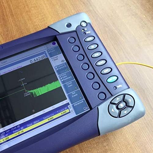
Image 6.1: A close-up of the MTS 6000 screen showing an active OTDR trace with event analysis.
6.3. Other Applications
The MTS 6000 platform supports additional applications:
- Optical Fault Locator: For quick identification of faults in short fiber segments.
- Optical Channel Analyzer: Specialized for CWDM network installation and maintenance.
- Automated Ethernet Tester: For 10/100/1000MB Ethernet network optimization.
- Micro OTDR (uOTDR): A full-featured OTDR in a compact package for specific network installations.
Refer to the on-screen help or advanced documentation for detailed instructions on these specific applications.
7. Maintenance
7.1. Cleaning the Unit
- Use a soft, lint-free cloth dampened with a mild cleaning solution (e.g., isopropyl alcohol) to clean the exterior of the unit.
- Never spray cleaning solutions directly onto the device.
- Keep optical ports clean using specialized fiber optic cleaning tools and procedures. Contaminated connectors can lead to inaccurate measurements and damage.
7.2. Battery Care
- To maximize battery life, avoid fully discharging the battery frequently.
- If storing the unit for an extended period, ensure the battery is charged to approximately 50-70%.
8. Troubleshooting
| Problem | Possible Cause | Solution |
|---|---|---|
| Unit does not power on. | Battery discharged; Power adapter not connected or faulty. | Connect to AC power and allow to charge. Verify power adapter functionality. |
| No OTDR trace displayed. | Fiber not connected; Dirty connector; Incorrect test parameters; Module not properly seated. | Ensure fiber is securely connected. Clean fiber connectors. Check test settings (wavelength, range). Verify module installation. |
| Inaccurate measurements. | Dirty connectors; Incorrect refractive index setting; Faulty launch/receive fiber. | Clean all fiber connectors. Verify refractive index setting. Inspect or replace launch/receive fibers. |
If the problem persists after attempting these solutions, contact customer support.
9. Specifications
The following are key specifications for the JDSU VIAVI MTS 6000 OTDR with E8126B module:
| Feature | Detail |
|---|---|
| Model | JDSU VIAVI MTS 6000 OTDR with E8126B module |
| Brand | USA-JDSU-VIAVI |
| OTDR Module | E8126B |
| Wavelengths | 1310nm / 1550nm |
| Dynamic Range | 42dB (1310nm) / 41dB (1550nm) |
| Dimensions (L x W x H) | 8 x 6 x 3 inches (Mainframe) |
| Item Weight | Approximately 11 pounds |
| Special Features | Compact, Lightweight, Modular platform |
| UPC | 723907964045 |
10. Warranty and Support
For warranty information and technical support, please refer to the documentation provided with your purchase or visit the official USA-JDSU-VIAVI website. Keep your proof of purchase for warranty claims.
For further assistance, contact your local distributor or the manufacturer's customer service department.