1. Introduction
The Hilitand NLQ3-125/4P Dual Power Automatic Transfer Switch (ATS) is designed to ensure a continuous power supply by automatically switching between a main power source and a standby power source. This device is crucial for emergency power systems in homes, factories, and other applications where uninterrupted power is essential. It features millisecond-level switching for seamless power transition.
This manual provides detailed instructions for the safe installation, operation, and maintenance of your NLQ3-125/4P ATS.
2. Safety Information
WARNING: Installation and maintenance should only be performed by qualified personnel. Failure to follow these instructions may result in electric shock, fire, or serious injury.
- Always disconnect all power sources before installing or servicing the ATS.
- Ensure proper grounding of the device.
- Verify all wiring connections are secure and correct according to the wiring diagram.
- Do not operate the switch if it appears damaged.
- Observe all local and national electrical codes.
3. Product Overview
The NLQ3-125/4P ATS is a compact, 4-pole device featuring both automatic and manual operation modes. It is constructed from flame-retardant PC plastic for safety and durability, with silver contacts for improved conductivity and extended service life.

Figure 3.1: Front view of the NLQ3-125/4P ATS, showing the main power (Source A) and generator (Source B) inputs, output terminals, and the manual/auto selector switch.

Figure 3.2: Angled view of the ATS, highlighting the robust terminal blocks for secure wiring connections.
Key Components:
- Source A (Normal Power) Terminals: For connecting the primary power supply.
- Source B (Generator) Terminals: For connecting the standby power supply.
- Output Terminals: For connecting to the load.
- Manual/Auto Selector Switch: Allows selection between automatic and manual operation modes.
- Indicator Lights: To show the active power source (A or B).
- Control Terminals: For external control signals (AR, AN, NC, C1, OFF, BR, BN, NC, C1, OFF).
4. Specifications
| Feature | Specification |
|---|---|
| Model | NLQ3-125/4P |
| Material | PC, Silver Contacts |
| Switch Type | Secondary Distribution |
| Rated Current | 63A |
| Rated Voltage | 110V AC |
| Insulation Voltage | 690V AC |
| Rated Frequency | 50/60Hz |
| Electrical Level | PC Level Isolation Type |
| Rated Impulse Withstand Voltage | 8KV |
| Operation Mode | Automatic, Manual |
| Mounting Type | DIN Rail Mount |
| Dimensions (Approx.) | 143mm x 96mm x 69mm (5.63in x 3.78in x 2.72in) |
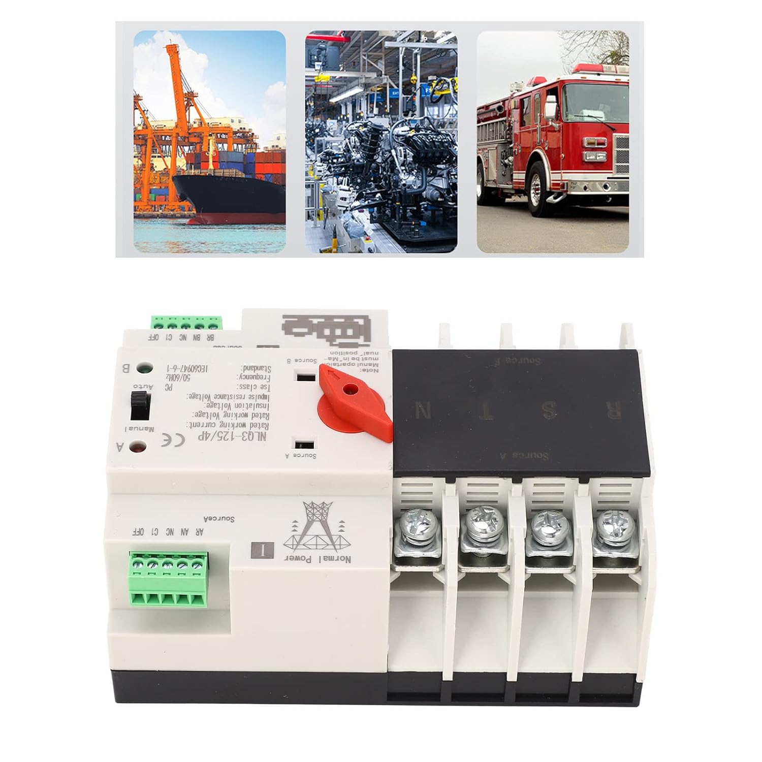
Figure 4.1: Approximate dimensions of the NLQ3-125/4P ATS for installation planning.
5. Installation and Setup
The NLQ3-125/4P ATS is designed for track installation and is compatible with PZ30 power distribution boxes. Before proceeding with installation, ensure all power is disconnected at the main breaker.
Installation Steps:
- Inspection: Before installation, carefully inspect the ATS for any signs of damage. Use the operating handle to manually switch it on and off to check the flexibility of the transmission mechanism. Verify the generation and disconnection conditions of the load at each stage for both normal and standby power supplies.
- Mounting: Mount the ATS securely onto a DIN rail within your PZ30 power distribution box or suitable enclosure.
- Wiring Main Power (Source A): Connect the main power supply (Normal Power) to the terminals labeled 'Source A'. Ensure correct phase (R, S, T) and neutral (N) connections for 4-pole systems.
- Wiring Standby Power (Source B): Connect the standby power supply (Generator) to the terminals labeled 'Source B'. Ensure correct phase (R, S, T) and neutral (N) connections.
- Wiring Load: Connect the load (your electrical system) to the output terminals of the ATS.
- Control Wiring: Connect any necessary external control signals to the AR, AN, NC, C1, OFF (for Source A) and BR, BN, NC, C1, OFF (for Source B) terminals as per your system requirements.
- Verification: Double-check all wiring for correctness and tightness. Ensure no loose connections are present.

Figure 5.1: Example wiring diagram for the NLQ3-125/4P ATS. Consult a qualified electrician for specific installation needs.
Environmental Conditions:
- Ambient Temperature: Maximum 40°C, minimum -5°C. The average temperature within 24 hours should not exceed 35°C.
- Altitude: Installation site altitude should not be higher than 2000m.
- Relative Humidity: At 40°C, relative humidity should not exceed 50%. At -5°C, higher humidity is permissible (e.g., 90% at 25°C). Special measures may be needed to address occasional condensation due to temperature changes.
6. Operating Instructions
The NLQ3-125/4P ATS offers both automatic and manual operation modes.
Automatic Mode:
- Set the selector switch to the 'Auto' position.
- In this mode, the ATS will continuously monitor the main power supply (Source A).
- If Source A fails or becomes abnormal, the ATS will automatically switch to the standby power supply (Source B) within milliseconds.
- When Source A is restored and stable, the ATS will automatically switch back to Source A.
- The indicator lights (A or B) will show which power source is currently active.
Manual Mode:
- Set the selector switch to the 'Manual' position.
- In manual mode, the user can manually switch between Source A and Source B using the operating handle.
- This mode is typically used for testing, maintenance, or in situations where automatic switching is not desired.
- Note: Ensure the manual operation is performed carefully and safely, especially when power is connected.
7. Maintenance
Regular maintenance ensures the longevity and reliable operation of your ATS.
- Periodic Inspection: Annually inspect the ATS for any signs of wear, damage, or loose connections.
- Cleaning: Keep the device clean and free from dust and debris. Use a dry, soft cloth for cleaning. Do not use liquid cleaners.
- Terminal Check: Periodically check all terminal screws to ensure they are tight and secure.
- Function Test: Regularly test the automatic switching function by simulating a main power failure (if safe to do so) to ensure the standby power engages correctly.
- Professional Service: For any complex issues or internal repairs, contact a qualified electrician or service technician.
8. Troubleshooting
This section addresses common issues you might encounter with your ATS.
Issue: ATS does not switch automatically.
- Check Mode: Ensure the selector switch is set to 'Auto' mode.
- Power Supply: Verify that both main (Source A) and standby (Source B) power supplies are connected and functional.
- Control Wiring: Inspect control wiring for any disconnections or faults.
- Internal Fault: If all external checks are clear, there might be an internal fault. Contact a qualified technician.
Issue: No power to load.
- Input Power: Check if both Source A and Source B have power.
- Switch Position: Ensure the ATS is switched to an active power source (either A or B, indicated by lights).
- Output Wiring: Inspect the wiring from the ATS output to the load for any breaks or loose connections.
- Overload/Short Circuit: Check for any overload or short circuit conditions in your electrical system that might have tripped protective devices upstream.
Issue: ATS makes unusual noises.
- Loose Components: Disconnect power and check for any loose internal components or mounting screws.
- Internal Damage: If the noise persists and cannot be identified, it may indicate internal damage. Seek professional assistance.
9. Warranty and Support
For warranty information and technical support, please refer to the documentation provided with your purchase or contact Hilitand customer service through their official channels. Keep your purchase receipt as proof of purchase.
Manufacturer: Hilitand
Model Number: NLQ3-125/4P


