
1. Introduction and Overview
This manual provides detailed instructions for the assembly, operation, and maintenance of your RIVECO 42U 19-inch Adjustable Depth Server Rack. This floor-standing 4-post rack is designed to support a wide range of 19-inch standard networking devices, offering adjustable depth, robust construction, and mobility.
Key features include:
- Adjustable Depth: The top and bottom frames can be adjusted from 24 inches (60cm) to 38 inches (95cm) to accommodate various equipment sizes.
- Durable Construction: Made from 2.0mm thick cold-rolled steel with an all-rivet structural connection for enhanced stability.
- High Load Capacity: Equipped with 3-inch load-bearing casters supporting up to 1200 lbs (static load) and leveling feet supporting up to 1700 lbs.
- Adjustable L Rails: Horizontal mounting rails provide additional structural stability and distribute equipment weight.
- Cable Management: Integrated cable management rings help keep cables organized.
2. Components and Package Contents
Before assembly, verify that all components listed below are present in your package. The rack comes in double-boxed packaging.

Figure 2.1: Overview of server rack components and included hardware.
Package Contents:
| Category | Item | Description |
|---|---|---|
| Rack Structure | Adjustable Depth Rack | Main frame of the server rack. |
| Mounting Hardware | M3 Screws | For light equipment mounting. |
| M6 Screws & Cage Nuts | For standard equipment mounting. | |
| M6 Hex Head Screws | For specific structural connections. | |
| Mobility & Stability | Casters | 3-inch load-bearing wheels for mobility. |
| Leveling Feet | For static stability and leveling on uneven surfaces. | |
| Accessories | Adjustable L Rails | Horizontal support rails (2 pairs for 22U-42U models). |
| Cable Management Rings | For organizing cables. | |
| Tools | Hex Wrench, L Wrench | Required for assembly. |
3. Setup and Assembly
Follow these steps carefully to assemble your RIVECO server rack. It is recommended to have two people for assembly due to the size and weight of the components.
3.1. Unpacking and Preparation
- Carefully unpack all components and lay them out on a clean, flat surface.
- Verify all parts against the package contents list in Section 2.
- Keep all packaging materials until assembly is complete and the rack is confirmed to be in working order.
3.2. Frame Assembly
The rack features an all-rivet structural connection for stability. Ensure all connections are secure during assembly.

Figure 3.1: Detail of the all-rivet structure for enhanced stability.
3.3. Adjustable Depth Configuration
The rack's depth can be adjusted to fit various equipment. This adjustment is made by sliding the top and bottom frames.

Figure 3.2: Illustration of the adjustable depth mechanism, ranging from 23.8" to 39.6".
- Loosen the securing bolts on the top and bottom frame sections.
- Slide the frame sections to achieve the desired mounting depth (between 24 inches and 38 inches).
- Securely tighten all bolts once the desired depth is set.
3.4. Caster and Leveling Feet Installation
Install either the casters for mobility or the leveling feet for static placement.

Figure 3.3: Close-up of the heavy-duty casters and the 2.0mm steel thickness.
- Attach the heavy-duty casters to the bottom of the rack if mobility is required. Ensure they are securely fastened.
- Alternatively, attach the leveling feet for a stationary setup. Adjust the feet to ensure the rack is level and stable on the floor.
3.5. Adjustable L Rails Installation
The L rails provide additional support for heavy equipment and enhance overall structural stability.
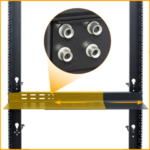
Figure 3.4: Adjustable L rails for equipment support and stability.
- Insert the L rails into the desired mounting positions on the rack posts.
- Adjust their depth to match your equipment and secure them using the provided screws.
4. Operating Instructions
Once assembled, the RIVECO server rack is ready for equipment installation and cable management.
4.1. Equipment Installation
Mount your 19-inch standard equipment (e.g., servers, network switches, UPS) using the provided M3 or M6 screws and cage nuts.

Figure 4.1: Example of network equipment installed within the server rack.
4.2. Cable Management
Utilize the integrated cable management rings to keep your cables neat and organized, preventing tangles and improving airflow.

Figure 4.2: Close-up of a cable management ring, designed to keep cables tidy.
5. Maintenance
Regular maintenance ensures the longevity and optimal performance of your server rack.
- Cleaning: Periodically wipe down the rack with a soft, dry cloth to remove dust and debris. Avoid abrasive cleaners.
- Fastener Check: Every 6-12 months, inspect all bolts and screws to ensure they are tight. Re-tighten if necessary to maintain structural integrity.
- Caster/Leveling Feet Inspection: If using casters, check for smooth operation and clean any accumulated debris. If using leveling feet, ensure they remain properly adjusted and stable.
- Cable Management: Regularly check cable routing to ensure no cables are pinched or obstructing airflow.
6. Troubleshooting
This section addresses common issues you might encounter with your server rack.
6.1. Rack Instability
- Issue: The rack feels wobbly or unstable.
- Solution:
- Ensure all assembly bolts, especially those connecting the main frame and adjustable depth sections, are securely tightened.
- If using leveling feet, adjust them to ensure all four corners are firmly on the ground and the rack is level.
- Verify that the L rails are properly installed and secured, as they contribute to overall stability.
6.2. Difficulty Mounting Equipment
- Issue: Equipment does not fit or is difficult to mount.
- Solution:
- Confirm your equipment is 19-inch rack-mountable.
- Check the adjustable depth setting. Ensure the rack's depth is sufficient for your equipment. Adjust if necessary (refer to Section 3.3).
- Ensure you are using the correct M3 or M6 screws and cage nuts for your equipment.
7. Specifications
Detailed technical specifications for the RIVECO 42U Server Rack.
| Specification | Detail |
|---|---|
| Brand | RIVECO |
| Model | 42U |
| Color | Black |
| Product Dimensions (D x W x H) | 38"D x 21"W x 78.8"H (Adjustable depth from 24" to 38") |
| Material | Alloy Steel, Plastic, Polycarbonate |
| Mounting Type | Floor Mount |
| Weight Capacity (Static Load) | Up to 1700 lbs (with leveling feet), 1200 lbs (with casters) |
| Compatible Devices | 19" standard equipment, Dell, HP, IBM, CISCO, LENOVO servers, rack mount devices |
| Assembly Required | Yes |
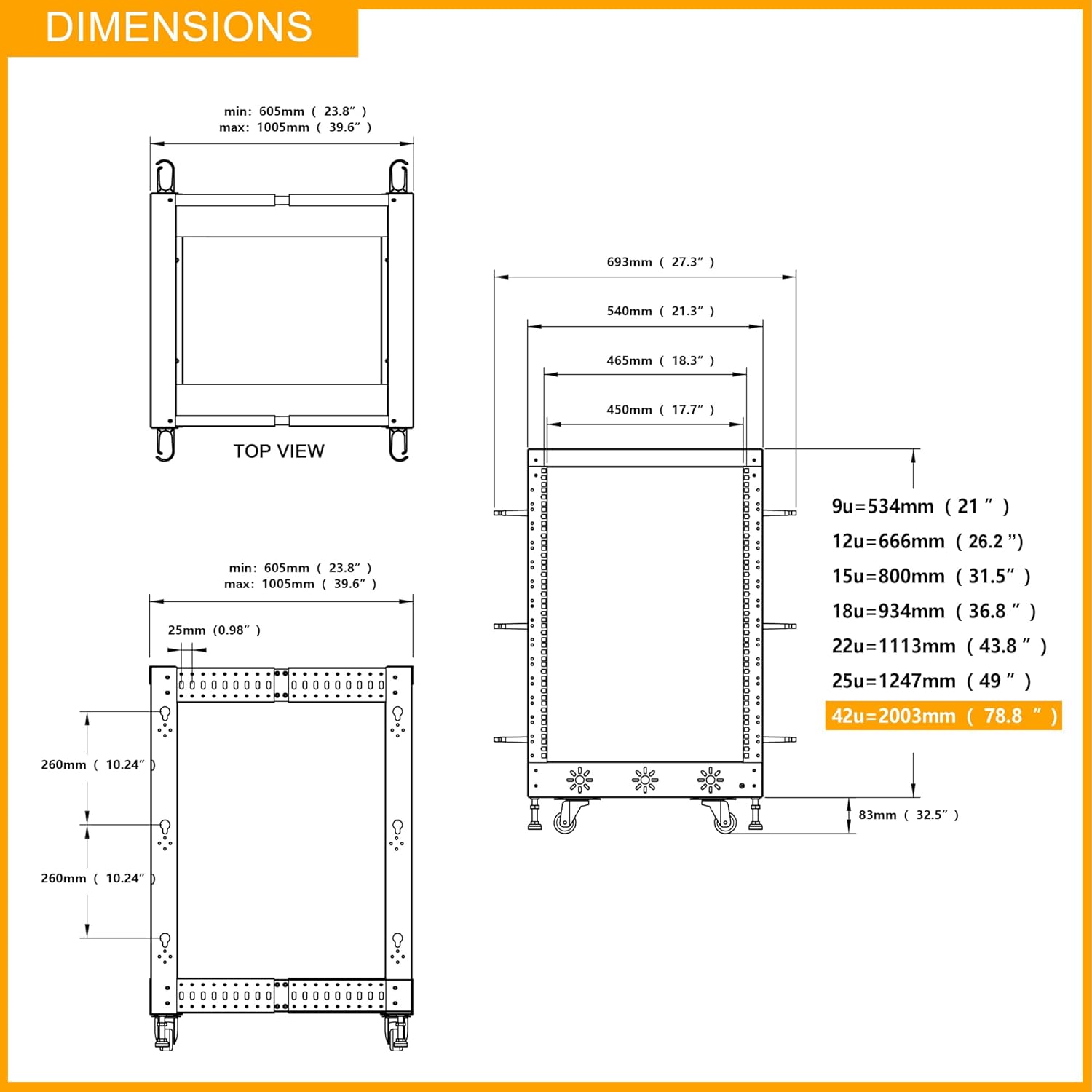
Figure 7.1: Detailed dimensions of the RIVECO 42U server rack, including top and side views.
8. Warranty and Support
RIVECO provides a warranty for this product and offers customer support.
- Warranty: This product comes with a 2-year warranty. Please retain your proof of purchase for warranty claims.
- Customer Support: For any questions, technical assistance, or warranty claims, please contact Riverside Trading Co.,Ltd. through the platform where you purchased the product or refer to the contact information provided with your purchase.
9. Product Video Overview
Watch the official product video for a visual guide on the RIVECO 19" 4 Post Adjustable Depth Server Rack with L Rails.
Video 9.1: Official RIVECO video showcasing the features and assembly of the 19" 4 Post Adjustable Depth Server Rack.