1. Introduction
This manual provides essential information for the safe and effective use of the Generic ZVS (Zero Voltage Switching) Tesla Coil Flyback Driver Board. This module is designed for high voltage boosting and induction heating applications, commonly used in projects such as spark gap Tesla coils (SGTC), Jacob's ladders, and Marx generators. Please read these instructions carefully before operation to ensure proper functionality and safety.
2. Safety Information
WARNING: This device operates at high voltages and can be dangerous if not handled properly. Always exercise extreme caution.
- Ensure all connections are secure and correct before applying power.
- Never touch the high voltage output terminals or any associated components while the device is powered on.
- Operate the module in a well-ventilated area to prevent overheating.
- Keep away from flammable materials.
- Use appropriate personal protective equipment (PPE), such as insulated gloves and safety glasses, when working with high voltage.
- Disconnect power immediately if any unusual behavior, smoke, or burning smell is observed.
- This product is intended for experienced users familiar with high voltage electronics.
3. Product Features
- Compact size: 74 mm x 77 mm.
- Wide input voltage range: 12V-30V DC (24V recommended).
- Operating frequency: 30KHz - 60KHz.
- Military-grade 1.6mm double-layer PCB with four 3mm mounting holes.
- Equipped with 30mm large heat sinks for improved stability and extended lifespan.
- Optimized component placement for better heat dissipation, especially for capacitors.
- Enhanced power line tinning for increased current-carrying capacity.
- High-precision metal film resistors with low temperature drift.

Figure 1: Top-down view of the ZVS Tesla Coil Flyback Driver Board, showing the main components including the inductor, capacitors, and heat sinks.
4. Specifications
| Parameter | Value |
|---|---|
| Input Voltage | 12V - 30V DC (24V Recommended) |
| Power Supply Current (Min) | > 5A (for < 15V input), > 15A (for >= 15V input) |
| Operating Frequency | 30KHz - 60KHz |
| Secondary Parameters | 5T + 5T |
| Board Dimensions | 74 mm x 77 mm |
| PCB Thickness | 1.6 mm (double board) |
| Mounting Holes | Four 3 mm holes |
Performance Characteristics
| Input Voltage | Output Voltage (Approx.) | Average Power | Maximum Power | Arc Length |
|---|---|---|---|---|
| 12V | 1000V | 50W | 100W | 2-4 CM |
| 24V | 2000V | 100W | 200W | 5-8 CM |
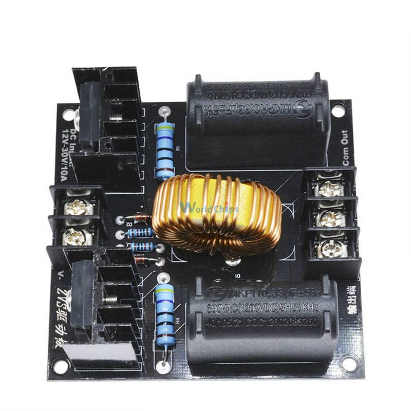
Figure 2: Detailed view of the ZVS driver board, highlighting the inductor, capacitors, and resistors.
5. Setup
Proper setup is crucial for the safe and efficient operation of the ZVS driver board. Follow these steps carefully:
5.1 Power Supply Requirements
- The input voltage range is 12V to 30V DC. A 24V DC power supply is recommended for optimal performance.
- For input voltages below 15V, a power supply capable of delivering at least 5A is required.
- For input voltages of 15V or higher, a power supply capable of delivering at least 15A is required.
- Ensure your power supply can provide the necessary current to avoid damage to the module or the power supply itself. For example, a 24V input can achieve over 200W, requiring a power supply current of more than 10A.
5.2 Connections
- Input Power: Connect your DC power supply to the "DC Input: 12V-30V/10A" terminals. Ensure correct polarity: V+ to positive, V- to negative.
- Output: Connect your load (e.g., Tesla coil primary, flyback transformer primary) to the "Out Com Out" terminals. The ZVS circuit is designed to drive an ignition coil.
- Secondary Coil Parameters: The module is designed for a secondary coil with 5T+5T windings.
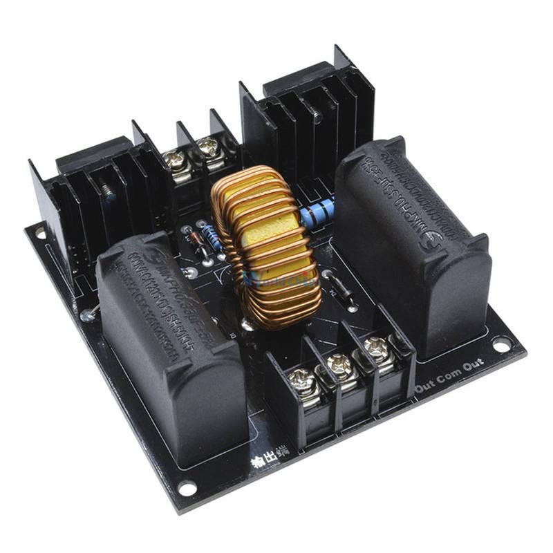
Figure 3: Angled view of the ZVS driver board, illustrating the input (DC Input) and output (Out Com Out) terminals for wiring.
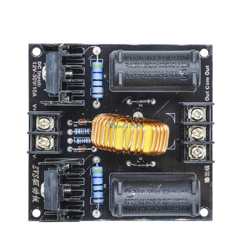
Figure 4: Top-down perspective of the ZVS driver board, providing a clear view of the labeled input and output terminals for connection.
6. Operating Instructions
Once the ZVS driver board is correctly set up and connected to a suitable load and power supply, you can proceed with operation.
6.1 Basic Operation
- Double-check all wiring to ensure correct polarity and secure connections.
- Ensure the load is properly connected and isolated from unintended contact.
- Apply power to the ZVS driver board. The circuit should begin oscillating, generating high voltage at the output.
- Monitor the module for any signs of overheating or abnormal operation.
- To power off, disconnect the input power supply.
6.2 Applications
The ZVS circuit, known for its Zero Voltage Switching, is widely used due to its high power, low heat generation, and reliable performance. Common applications include:
- Spark Gap Tesla Coils (SGTC): Driving the primary coil of a Tesla coil to generate high frequency, high voltage discharges.
- Jacob's Ladders: Creating a climbing electric arc between two diverging electrodes.
- Marx Generators: Used as a high voltage pulse generator.
- Induction Heating: For small-scale induction heating experiments.
7. Maintenance
The ZVS driver board is designed for durability, but proper maintenance can extend its lifespan and ensure consistent performance.
- Heat Management: The module includes large heat sinks. Ensure they are kept clear of obstructions to allow for adequate airflow. Periodically check for dust accumulation and clean gently with compressed air if necessary.
- Connections: Regularly inspect all wiring connections for looseness or corrosion. Tighten terminals as needed.
- Visual Inspection: Periodically inspect the PCB for any signs of damage, such as burnt components, cracked solder joints, or bulging capacitors.
- Storage: When not in use, store the module in a dry, cool environment, away from direct sunlight and moisture.
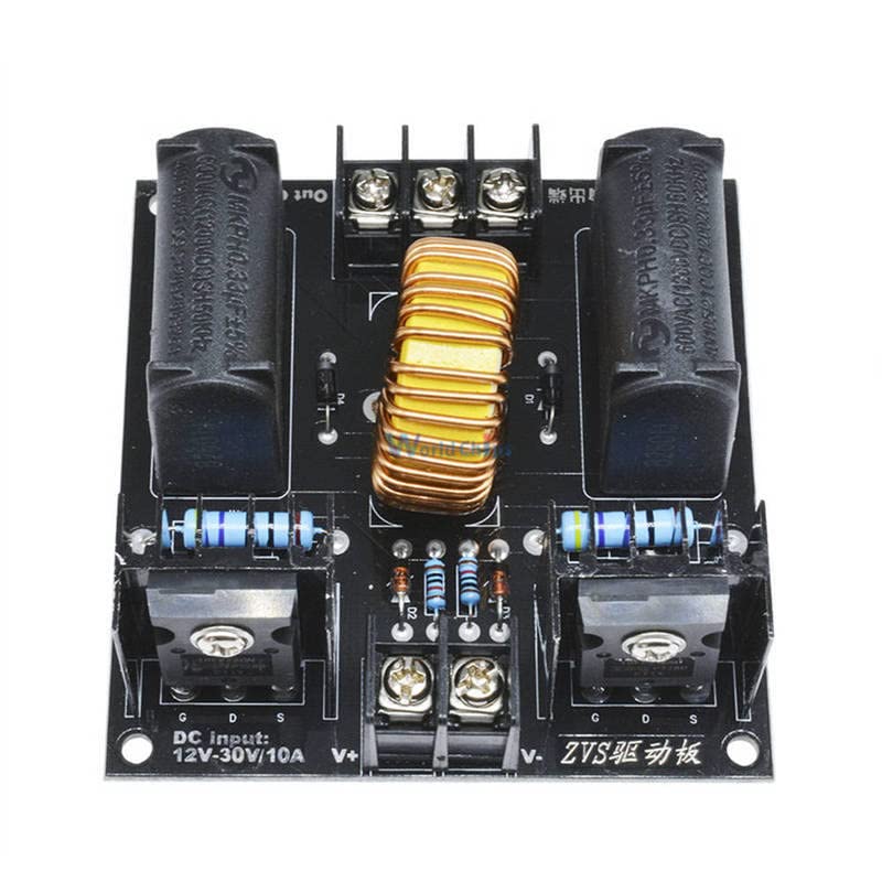
Figure 5: Angled view of the ZVS driver board, emphasizing the heat sinks attached to the power transistors, crucial for thermal management.
8. Troubleshooting
If you encounter issues with your ZVS driver board, consider the following common problems and solutions:
- No Output/No Oscillation:
- Check input power supply: Ensure it meets the voltage and current requirements. A weak power supply is a common cause.
- Verify input polarity: Incorrect DC input polarity will prevent operation and may damage the board.
- Inspect connections: Ensure all wires are securely connected to the terminals.
- Check the load: Ensure the load (e.g., flyback transformer primary) is correctly connected and not short-circuited or open-circuited.
- Excessive Heat:
- Ensure adequate ventilation around the heat sinks.
- Verify the input current is not exceeding the board's limits for prolonged periods.
- Check for short circuits in the load or output wiring.
- Intermittent Operation:
- Loose connections can cause intermittent operation. Re-tighten all terminals.
- A power supply that cannot consistently deliver the required current may lead to unstable operation.

Figure 6: Bottom view of the ZVS driver board, showing the PCB traces and solder points. This view can be useful for advanced troubleshooting or repair.
9. Warranty and Support
This Generic ZVS Tesla Coil Flyback Driver Board is manufactured to high standards. While specific warranty details are not provided, please ensure you follow all instructions and safety guidelines to prevent damage and ensure proper operation.
For technical support or inquiries, please refer to the seller or manufacturer's contact information provided at the point of purchase. Always provide your product model number (B0C5QXCSPG) when seeking assistance.