
1. Product Overview
The HARMNEE Industrial Grade PWM DC Motor Speed Controller is designed for precise speed regulation of DC brush motors. This robust controller features a wide input voltage range, high current capacity, and essential safety components, making it suitable for various industrial and hobby applications. It includes a CW/CCW switch for directional control and a potentiometer knob for stepless speed adjustment.

Image 1.1: Overview of the HARMNEE DC Motor Speed Controller, showing its compact design and integrated controls.
2. Technical Specifications
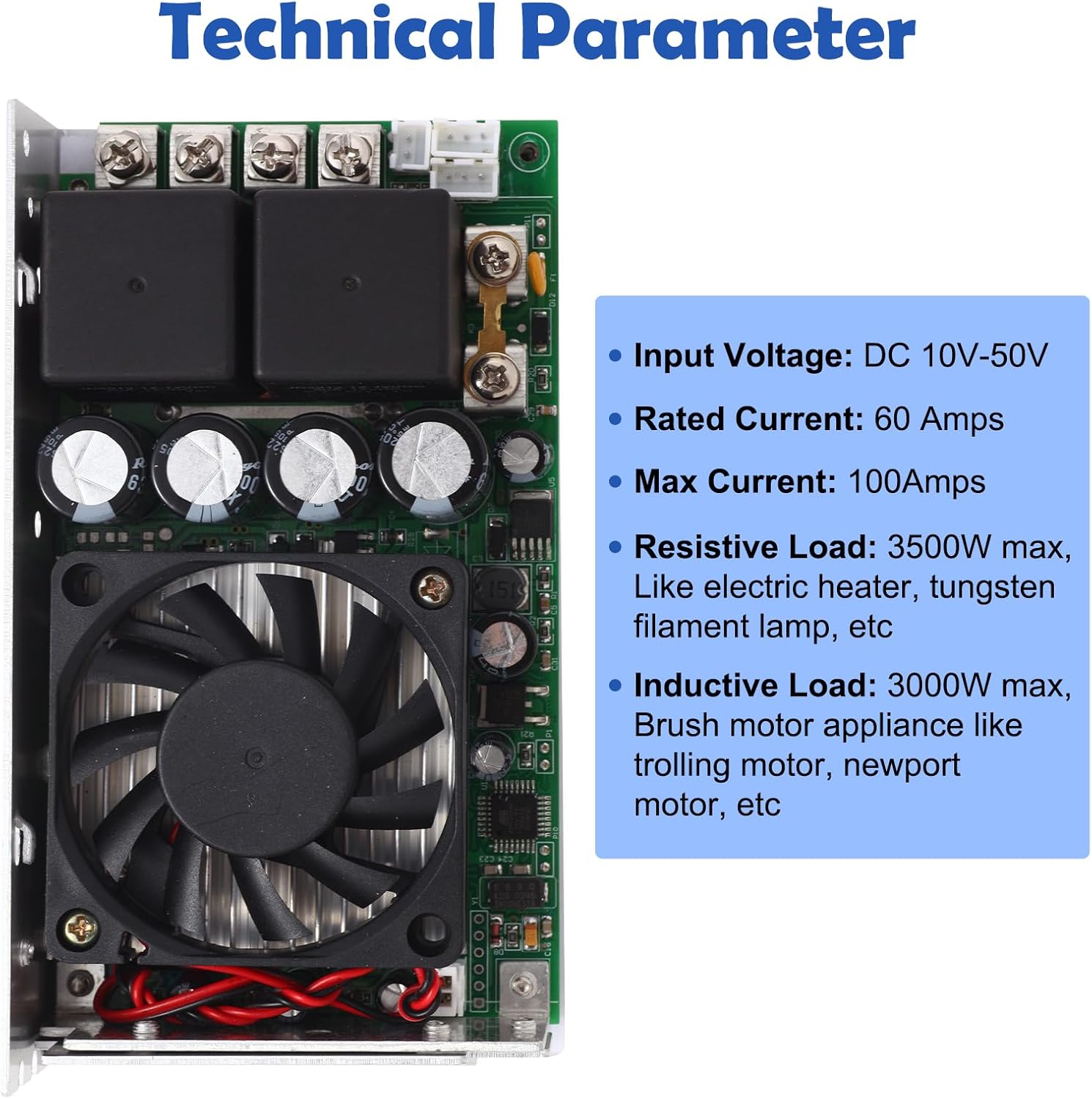
Image 2.1: Detailed view of the controller's technical parameters.
| Parameter | Value |
|---|---|
| Input Voltage | DC 10V-50V |
| Rated Current | 60A |
| Maximum Current | 100A |
| Speed Range | 0%-100% |
| Applicable Motor | DC Brush Motor |
| Resistive Load (Max) | 3500W (e.g., electric heater, tungsten filament lamp) |
| Inductive Load (Max) | 3000W (e.g., trolling motor, Newport motor) |
| Product Dimensions (L x W x H) | 5.7" x 3.1" x 1.5" |
| Item Weight | 1.02 Pounds |
| Material | Copper |
| Display Type | LED |
3. Product Features
- Cooling Fan: Equipped with a professional cooling fan to ensure effective heat dissipation and maintain safe operating temperatures, enhancing the controller's stability and lifespan.
- CW/CCW Switch: A dedicated switch allows for easy selection between clockwise and counter-clockwise motor rotation, providing versatile control for various applications.
- Ring Terminals: Includes ring terminals for secure and reliable connections between the motor, power supply, and the controller, minimizing wiring issues.
- Safety Fuse: Features a built-in fuse on the circuit board to protect the controller from damage due to excessive current. A spare fuse is included for replacement.
- Potentiometer Knob: Provides smooth, stepless speed adjustment from 0% to 100% of the motor's maximum speed.
4. Setup and Installation
4.1 Wiring Connections
Carefully follow the wiring diagram to connect the power supply and the DC brush motor to the controller. Ensure all connections are secure and correct to prevent damage to the unit or connected devices.
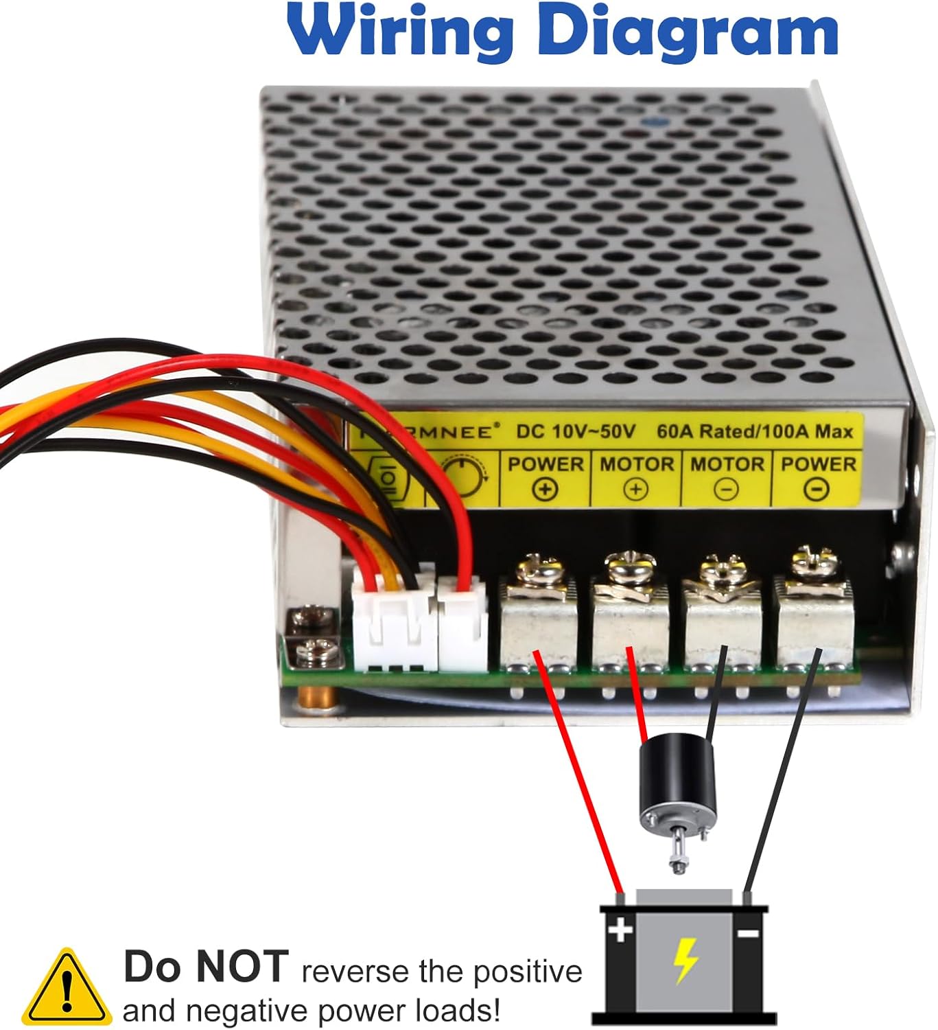
Image 4.1: Wiring diagram showing connections for power and motor. Pay close attention to polarity.
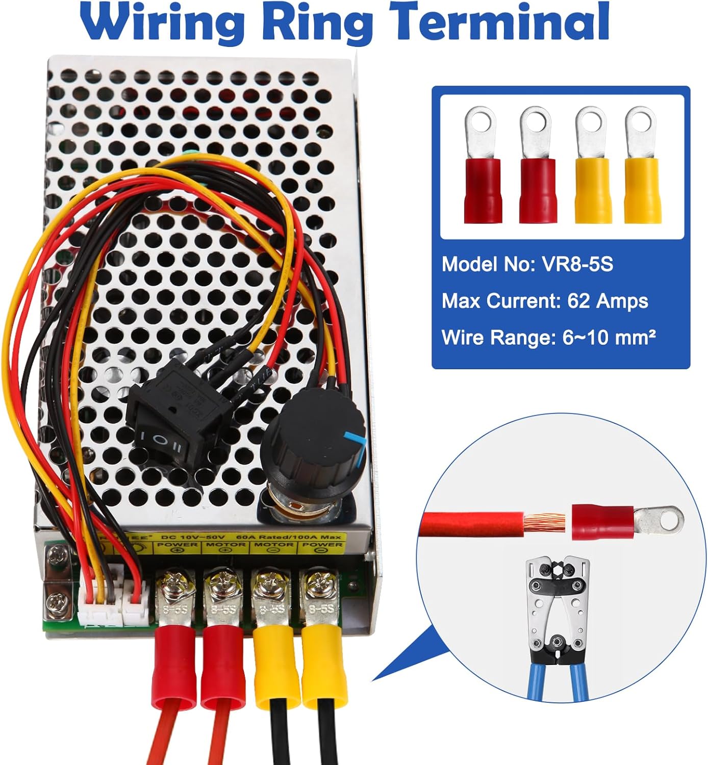
Image 4.2: Example of using ring terminals for robust and safe connections.
WARNING: Do NOT reverse the positive and negative power loads. Incorrect polarity can cause severe damage to the controller and connected equipment.
4.2 Environmental Considerations
The controller is designed with a cooling fan for heat dissipation. To ensure optimal performance and longevity, avoid installing the controller in a sealed enclosure without adequate ventilation. Proper airflow is crucial for maintaining safe operating temperatures.

Image 4.3: The integrated cooling fan requires proper ventilation. Do not install in a sealed box.
5. Operating Instructions
5.1 Power On/Off
Ensure all connections are correct before applying power. Use the main power switch (if applicable in your setup) to turn the controller on or off.
5.2 Speed Control
Rotate the potentiometer knob clockwise to increase motor speed and counter-clockwise to decrease it. The speed can be adjusted smoothly from 0% (off) to 100% (full speed).
5.3 Direction Control
Use the CW/CCW switch to select the desired direction of motor rotation. It is recommended to adjust the speed to zero or turn off the motor before changing direction to prevent sudden stress on the motor and controller.
6. Maintenance
6.1 Fuse Replacement
The controller is equipped with a safety fuse. If the controller stops functioning due to an overcurrent event, the fuse may have blown. To replace the fuse:
- Disconnect all power from the controller.
- Locate the fuse on the circuit board (it is typically a small metal strip held between two pins).
- Carefully remove the blown fuse.
- Insert the spare fuse provided into the fuse holder. Ensure it is properly seated.
- Reconnect power and test the controller.

Image 6.1: Visual guide for locating and replacing the safety fuse.
6.2 Cleaning and Inspection
Periodically inspect the controller for dust accumulation, especially around the cooling fan and ventilation holes. Clean with a soft, dry brush or compressed air. Ensure all wiring connections remain tight and free from corrosion.
7. Troubleshooting
If the controller is not functioning as expected, consider the following:
- No Power: Check the power supply connections and ensure the input voltage is within the specified DC 10V-50V range. Verify that the safety fuse is intact and not blown.
- Motor Not Responding: Confirm that the motor is correctly wired to the controller and that the CW/CCW switch is in a valid position. Check motor connections for looseness or damage.
- Inconsistent Speed: Ensure the potentiometer knob is clean and free from obstructions. Verify that the motor is not overloaded beyond its or the controller's capacity.
- Overheating: Check for proper ventilation around the controller. Ensure the cooling fan is operating correctly and not obstructed. Reduce the load if continuous overheating occurs.
8. Safety Information
Always prioritize safety when working with electrical components. Adhere to the following guidelines:
- Ensure all power is disconnected before making any wiring changes or performing maintenance.
- Do not exceed the specified input voltage (DC 10V-50V) or current ratings (Rated 60A, Max 100A).
- Avoid installing the controller in environments with excessive moisture, dust, or corrosive substances.
- Provide adequate ventilation for the controller to prevent overheating. Do not enclose it in a sealed box.
- Always double-check wiring polarity before applying power. Incorrect polarity can cause irreversible damage.
- Keep the device out of reach of children.
9. Warranty and Support
HARMNEE is committed to providing quality products and customer satisfaction. If you encounter any issues or have questions regarding your Industrial Grade PWM DC Motor Speed Controller, please contact HARMNEE customer service through Amazon. Our support team is available to provide timely assistance and after-sales service.
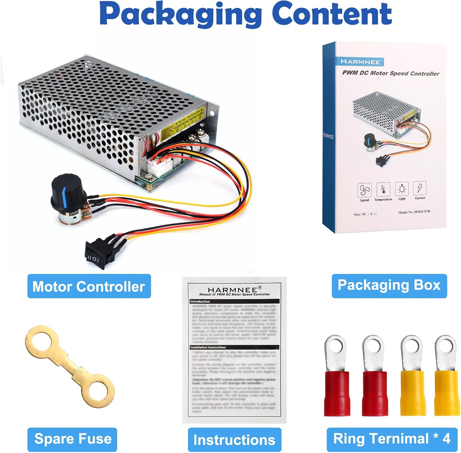
Image 9.1: Packaging content, including the motor controller, spare fuse, instructions, and ring terminals.