1. Introduction
The Jyving SM852B is a versatile digital phase indicator and rotation tester designed for electrical professionals. This device efficiently checks the phase sequence and identifies open phases in 3-phase AC systems. Its compact design and clear LED and buzzer indications ensure safe and reliable operation across a wide voltage range.
2. Product Features
- Dual Functionality: Checks phase sequence and indicates open phases.
- Wide Voltage Range: Operates from 60V to 600V AC three-phase.
- Safe and Reliable: Equipped with clips for secure connection to control panel terminals.
- Clear Indication: Features LED lights for phase status and a buzzer for audible alerts.
- Portable Design: Small and lightweight for easy transport and use.
- Durable Construction: Made from plastics and metal for longevity.
3. Product Components
The SM852B 3-Phase Rotation Tester includes the main unit, three test probes (yellow, green, red), and a wrist strap. The test probes are designed for secure connections to electrical systems.
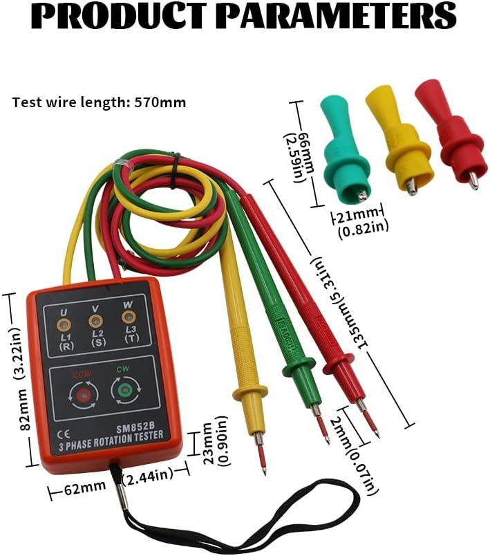
Figure 3.1: Product Components. The image displays the SM852B tester with its attached yellow, green, and red test leads, along with separate test clamps. Labels indicate the test clamp, test wizard (yellow for L1, green for L2, red for L3), open phase detection LEDs, phase continuous check LEDs, and wrist strap.

Figure 3.2: Front view of the SM852B tester with its attached test leads and alligator clips. The main unit is orange with indicator LEDs and buttons, and the leads are yellow, green, and red.

Figure 3.3: Rear view of the SM852B tester, displaying the test leads and clips. The back of the unit is orange, similar to the front, with the leads coiled.
4. Setup and Connection
Before use, ensure the test probes are securely attached to the main unit. The yellow probe connects to L1 (U/R), the green probe to L2 (V/S), and the red probe to L3 (W/T). The included test clamps can be attached to the probe tips for easier and safer connection to terminals.
Video 4.1: This video demonstrates the assembly of the test probes by attaching the protective caps and then the alligator clips to the probe tips. It shows how to prepare the SM852B tester for use.
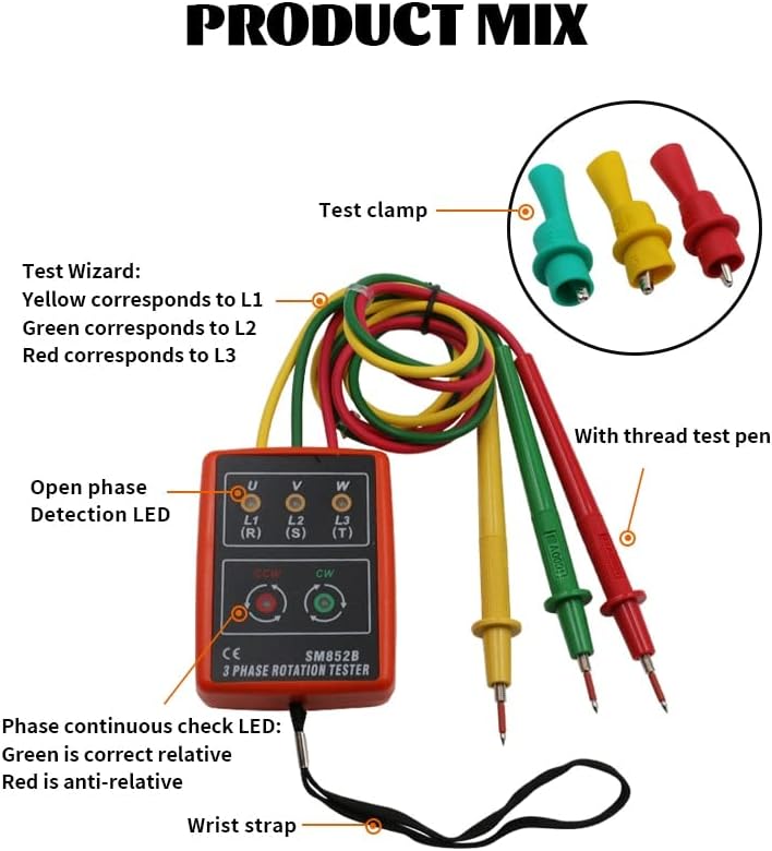
Figure 4.1: The SM852B tester in use, with its probes connected to an electrical circuit board, demonstrating a typical application for phase testing.
5. Operating Instructions
The SM852B tester is designed for straightforward operation. Connect the test probes to the three phases (L1, L2, L3) of the AC system you wish to test. The device will automatically detect the phase sequence and indicate open phases using its LEDs and buzzer.
5.1. Interpreting Indicators
The tester provides visual (LED) and audible (buzzer) feedback:
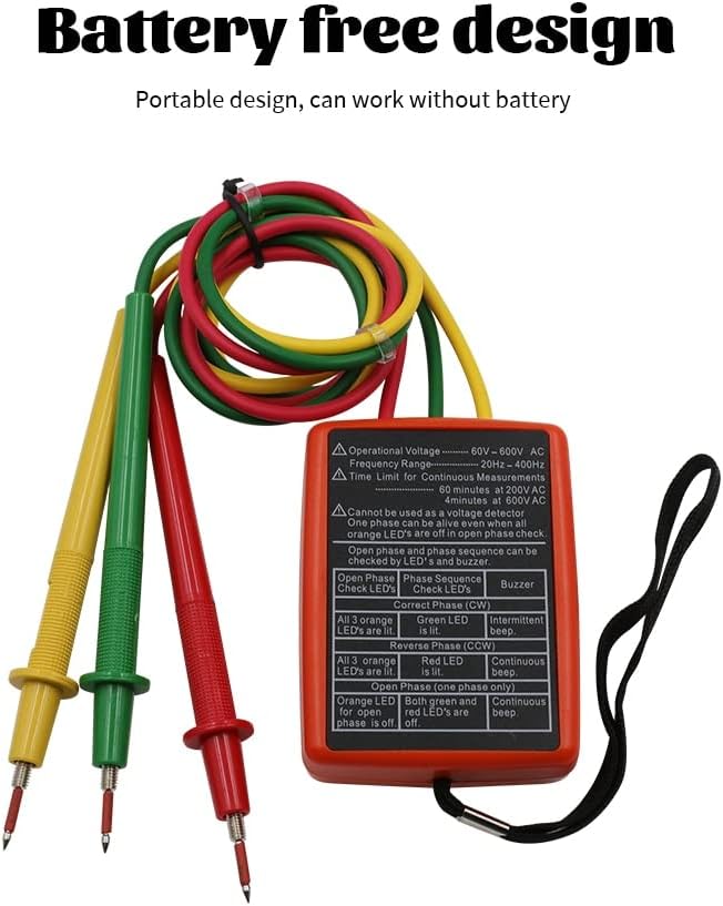
Figure 5.1: The back label of the SM852B tester, detailing operational voltage (60V-600V AC), frequency range (20Hz-400Hz), and continuous use time limits. It also includes a table explaining LED and buzzer indications for correct phase sequence (CW), reverse phase sequence (CCW), and open phase conditions.
| Condition | Check LEDs | Phase Sequence LEDs | Buzzer |
|---|---|---|---|
| Correct Phase Sequence (CW) | All 3 orange LEDs lit | Green LED lit | Intermittent beep |
| Reverse Phase Sequence (CCW) | All 3 orange LEDs lit | Red LED lit | Continuous beep |
| Open Phase (one phase only) | Orange LED for open phase is off | Both green and red LEDs are off | Continuous beep |
5.2. Continuous Use Time Limits
To prevent damage to the device, observe the following continuous use time limits:
- At 60V-AC: 60 minutes maximum.
- At 600V-AC: 4 minutes maximum.
6. Specifications
Detailed technical specifications for the Jyving SM852B 3-Phase Rotation Tester:
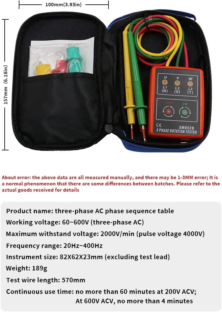
Figure 6.1: Product dimensions. The image shows the main unit with dimensions 82mm (3.22in) x 62mm (2.44in) x 23mm (0.90in), and the test pens with a length of 135mm (5.31in) and tip length of 2mm (0.07in).
- Product Name: Three-phase AC phase sequence table
- Material: Plastics + Metal
- Operation Voltage: 60V ~ 600V AC three-phase
- Limit Support Voltage: 2000V/minute (impulse voltage 4000V)
- Operation Frequency Range: 20Hz ~ 400Hz
- Instrument Size (excluding test lead): 82mm x 62mm x 23mm (3.22in x 2.44in x 0.90in)
- Weight: 189g
- Test Wire Length: 570mm
- Continuous Use Time:
- 60 minutes maximum at 60V-AC
- 4 minutes maximum at 600V-AC
7. Safety Information
Always prioritize safety when working with electrical systems. Read and understand all instructions before using the device. Wear appropriate personal protective equipment (PPE), such as insulated gloves and safety glasses. Do not exceed the specified voltage or continuous use limits. If the device appears damaged or malfunctions, discontinue use immediately. Ensure connections are secure before applying power.
8. Maintenance
To ensure the longevity and accuracy of your SM852B tester:
- Cleaning: Wipe the device with a soft, dry cloth. Do not use abrasive cleaners or solvents.
- Storage: Store the tester in a cool, dry place, away from direct sunlight and extreme temperatures. Keep it in its protective case when not in use.
- Inspection: Periodically inspect the test leads and probes for any signs of wear, cuts, or damage. Replace damaged components immediately.
9. Troubleshooting
If the device does not function as expected, consider the following:
- No Indication: Ensure all test probes are securely connected to the phases. Verify that the voltage is within the operational range (60V-600V AC).
- Incorrect Indication: Double-check the connections to ensure they correspond to the correct phases (L1, L2, L3).
- Device Damage: If the device has been dropped or exposed to moisture, it may be damaged. Do not attempt to repair it yourself.
10. Warranty and Support
For warranty information, technical support, or service inquiries, please refer to the documentation provided with your purchase or contact Jyving customer service directly. Keep your purchase receipt as proof of purchase.