Introduction
The QIWO QW-BLD-300 is a high-performance 3-phase Brushless DC (BLDC) motor controller designed for 60/86 flange motors. It operates within a voltage range of 12VDC to 56VDC and is capable of driving BLDC motors equipped with Hall sensors. This driver incorporates advanced technology to deliver high speed, high efficiency, low noise, and low vibration. It includes essential protection features such as overcurrent protection, overload protection, locked-rotor protection, and phase line short protection. The QW-BLD-300 also provides alarm output, speed signal output, and controls for positive/negative rotation. It is suitable for various applications including small equipment, electric power tools, exhaust fans, jade grinding machines, and vibrating motors.
Important Notes Before Installation
- Confirm that your motor is a brushless motor.
- Ensure that your motor has eight wires.
- The wiring diagrams provided in this manual refer to the wiring configuration that matches QIWO motors. If your motor's wire definition differs, a matching test is required. Adjust wiring until the motor operates correctly in both forward and reverse directions, indicating successful motor and driver wiring.
Setup and Wiring
Proper wiring is crucial for the safe and correct operation of the BLDC motor driver. Refer to the diagrams below for connection details.
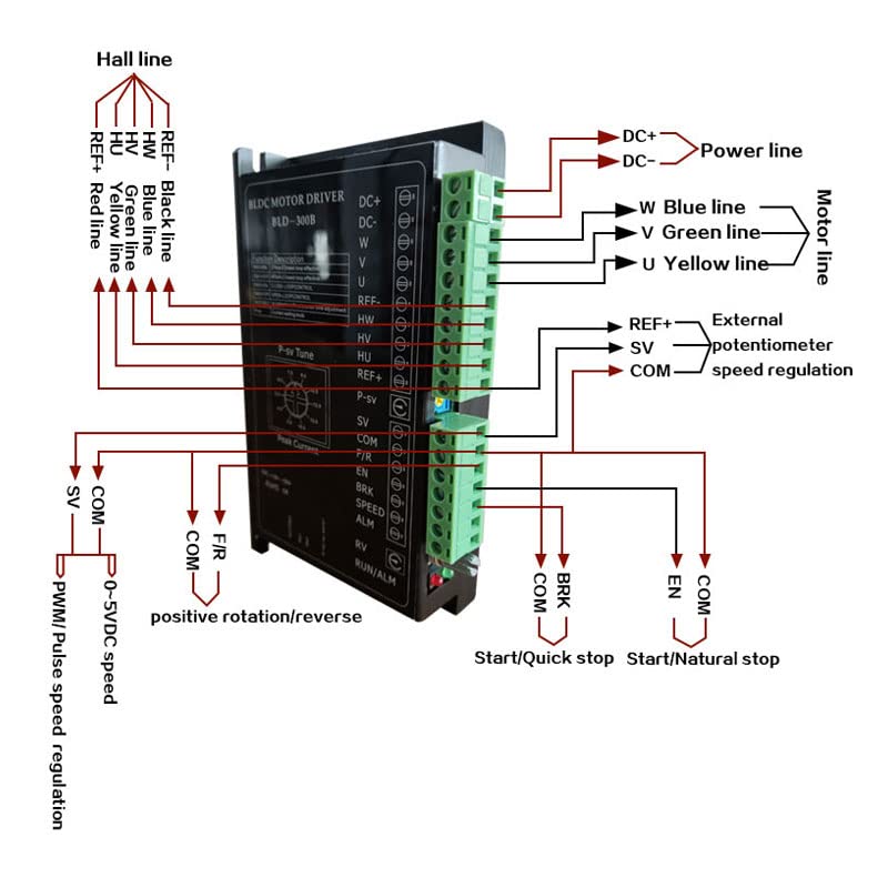
Figure 1: Comprehensive Wiring Diagram for BLD-300 Motor Driver. This diagram illustrates connections for the Hall line (REF-, HW, HV, HU, REF+), Power line (DC+, DC-), Motor line (W, V, U), and external control signals including potentiometer speed regulation (REF+, SV, COM), positive/reverse rotation (F/R, COM), start/quick stop (BRK, COM), and start/natural stop (EN, COM).
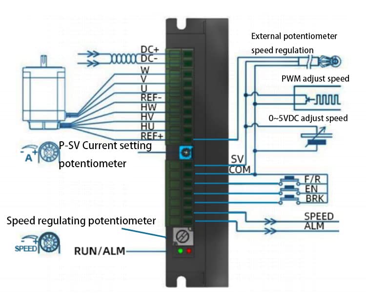
Figure 2: Detailed Control Signal Wiring. This diagram focuses on the connections for external speed regulation methods (potentiometer, PWM, 0-5VDC), current setting (P-SV potentiometer), and control inputs for F/R (forward/reverse), EN (enable), BRK (brake), SPEED (speed signal output), and ALM (alarm output).
Operating Instructions
1. Speed Regulation Modes
- External Potentiometer Control:
Use a 10KΩ potentiometer. Connect the middle terminal of the potentiometer to the SV terminal on the driver. Connect the other two terminals of the potentiometer to the REF+ terminal and the COM terminal, respectively.
- External 0-5VDC Voltage Control:
Apply an external voltage between 0-5VDC to the SV terminal. When the input voltage is approximately 0.25V, the motor speed will be 5% of its maximum. When the input voltage is approximately 4.7V, the motor will operate at its maximum speed.
2. Alarm Output (ALM Signal)
The ALM terminal provides a fault output signal. Under normal operating conditions, the output level is 5V. If a motor or driver fault occurs, the level will drop to 0V.
3. Positive/Reverse Rotation Function (F/R)
- Anticlockwise Rotation: Apply a low-level input to the F/R terminal, or connect the F/R terminal directly to the COM terminal.
- Clockwise Rotation: Apply a high-level input to the F/R terminal.
4. Start-Stop Function (EN)
- Motor Run: Apply a low-level input to the EN terminal, or connect the EN terminal directly to the COM terminal.
- Motor Slow Stop: Apply a high-level input to the EN terminal. The motor will gradually decelerate to a stop.
5. Braking Function (BRK)
- Motor Run (No Brake): Apply a low-level input to the BRK terminal, or connect the BRK terminal directly to the EN terminal.
- Motor Brake Stop: Apply a high-level input to the BRK terminal, or leave the port suspended. The motor will actively brake to a stop.
6. Peak Current Setting (P-SV Knob)
The driver includes a motor protection function that allows setting the desired peak current using the P-SV knob. Adjust this knob to set the current limit. Note that the rate of change for this setting is ±10%.
7. Acceleration/Deceleration Time Setting (ACC/DEC Potentiometer)
Adjust the acceleration and deceleration times of the motor using the ACC/DEC potentiometer. Rotating the potentiometer left or right will increase or decrease these times. The setting range is 0.3 to 15 seconds.
- Acceleration Time: The duration required for the motor to reach its rated speed from a static state.
- Deceleration Time: The duration required for the motor to stop from its rated speed.
8. Motor Pole Number Setting (SW1)
To ensure compatibility with brushless DC motors having different pole pairs, the number of motor poles can be set via DIP switch SW1.
- ON: Sets the motor to 2 poles (2P).
- OFF: Sets the motor to 4 poles (4P).
Note: When operating in closed-loop control, ensure SW1 is set according to the corresponding motor pole pairs.
9. Open/Closed Loop Control Setting (SW2)
Select between open-loop and closed-loop control modes using DIP switch SW2.
- ON: Activates closed-loop control.
- OFF: Activates open-loop control.
Note: When operating in closed-loop control, ensure the SV setting is adjusted according to the corresponding motor pole pairs.
Dimensions
Refer to the following diagrams for the physical dimensions of the QW-BLD-300 motor driver.
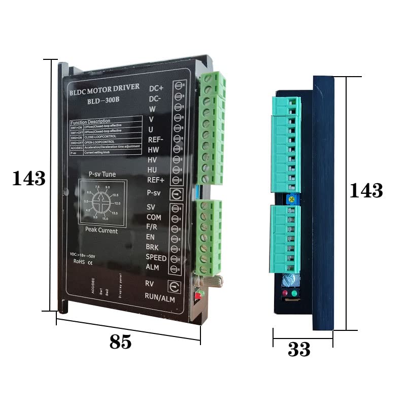
Figure 3: Front and Side Dimensions. This image displays the height (143 units), width (85 units), and depth (33 units) of the motor driver.
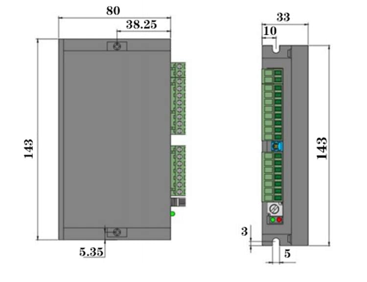
Figure 4: Detailed Technical Dimensions. This drawing provides precise measurements including mounting hole positions (e.g., 38.25 units apart), overall height (143 units), width (80 units), and depth (33 units), along with other minor dimensions (3, 5, 10 units).
Maintenance
To ensure the longevity and optimal performance of your QIWO QW-BLD-300 BLDC Motor Driver, follow these general maintenance guidelines:
- Keep Clean: Regularly inspect the driver for dust and debris accumulation. Use a soft, dry brush or compressed air to gently clean the vents and surfaces. Ensure power is disconnected before cleaning.
- Environmental Conditions: Operate the driver within its specified temperature and humidity ranges. Avoid exposure to excessive moisture, corrosive gases, or extreme temperatures.
- Connection Integrity: Periodically check all wiring connections to ensure they are secure and free from corrosion. Loose connections can lead to intermittent operation or damage.
- Ventilation: Ensure adequate airflow around the driver to prevent overheating. Do not obstruct ventilation openings.
Troubleshooting
If you encounter issues with your QW-BLD-300 motor driver, consider the following:
- No Motor Movement:
- Verify power supply connections (DC+, DC-).
- Check motor phase (U, V, W) and Hall sensor (HU, HV, HW) connections.
- Ensure the EN (Start-Stop) terminal is at a low level or connected to COM.
- Confirm the F/R (Positive/Reverse) terminal is correctly set for desired rotation.
- Check the speed regulation input (SV) for a valid signal (potentiometer or 0-5VDC).
- Motor Runs Erratically or with High Noise:
- Recheck Hall sensor wiring for correct phase sequence.
- Ensure motor pole number setting (SW1) matches your motor.
- Verify open/closed loop control setting (SW2) is appropriate for your application.
- Inspect motor phase connections for loose wires or poor contact.
- Alarm Output (ALM) is 0V:
A 0V output on the ALM terminal indicates a fault condition. This could be due to overvoltage, overcurrent, or locked-rotor protection activation. Investigate the motor and power supply for issues. Disconnect power, check for obstructions, and re-power the system.
- Overheating:
- Ensure adequate ventilation around the driver.
- Check if the motor load exceeds the driver's capacity.
- Verify the peak current setting (P-SV knob) is not excessively high for the motor.
Specifications
| Feature | Specification |
|---|---|
| Brand | QIWO |
| Model Name | BLD-300 |
| Voltage Range | 12VDC to 56VDC |
| Rated Speed | 3000 RPM |
| Horsepower Equivalent | 1000 Watts |
| Material | Aluminum |
| Item Weight | 0.35 Kilograms (12.3 ounces) |
| UPC | 752259627971 |
What's in the Box
- 1 x QIWO QW-BLD-300 BLDC Motor Driver Controller
Warranty and Support
For warranty information and technical support, please refer to the documentation provided with your purchase or contact QIWO customer service directly. Keep your purchase receipt for warranty claims.
For further assistance, you may visit the manufacturer's website or contact their support channels. Ensure you have your product model number (BLD-300) and any relevant purchase details ready when seeking support.