1. Introduction
This manual provides essential information for the safe and efficient operation of the Generic CHF100A-1R5G-S2 Inverter VFD Frequency AC Drive. This device is designed to control the speed and torque of AC induction motors by varying the frequency and voltage of the power supplied to the motor. Please read this manual thoroughly before installation, operation, or maintenance.
2. Safety Information
WARNING: Failure to follow these safety instructions may result in serious injury or death.
- This device operates with high voltage and current. Only qualified personnel should perform installation, wiring, and maintenance.
- Always disconnect power before working on the inverter. Wait at least 10 minutes after disconnecting power to allow DC Bus capacitors to discharge completely. Verify with a voltmeter that the DC bus voltage is zero before touching any components.
- Ensure proper grounding techniques are used for the inverter and the motor to prevent electric shock.
- Protect the inverter from moisture, dust, corrosive gases, and direct sunlight.
- Do not operate the inverter with damaged cables or if the enclosure is open or damaged.
3. Product Overview and Control Panel
The CHF100A-1R5G-S2 is a compact Variable Frequency Drive designed for precise motor control. Below is an image of the control panel with its key components.
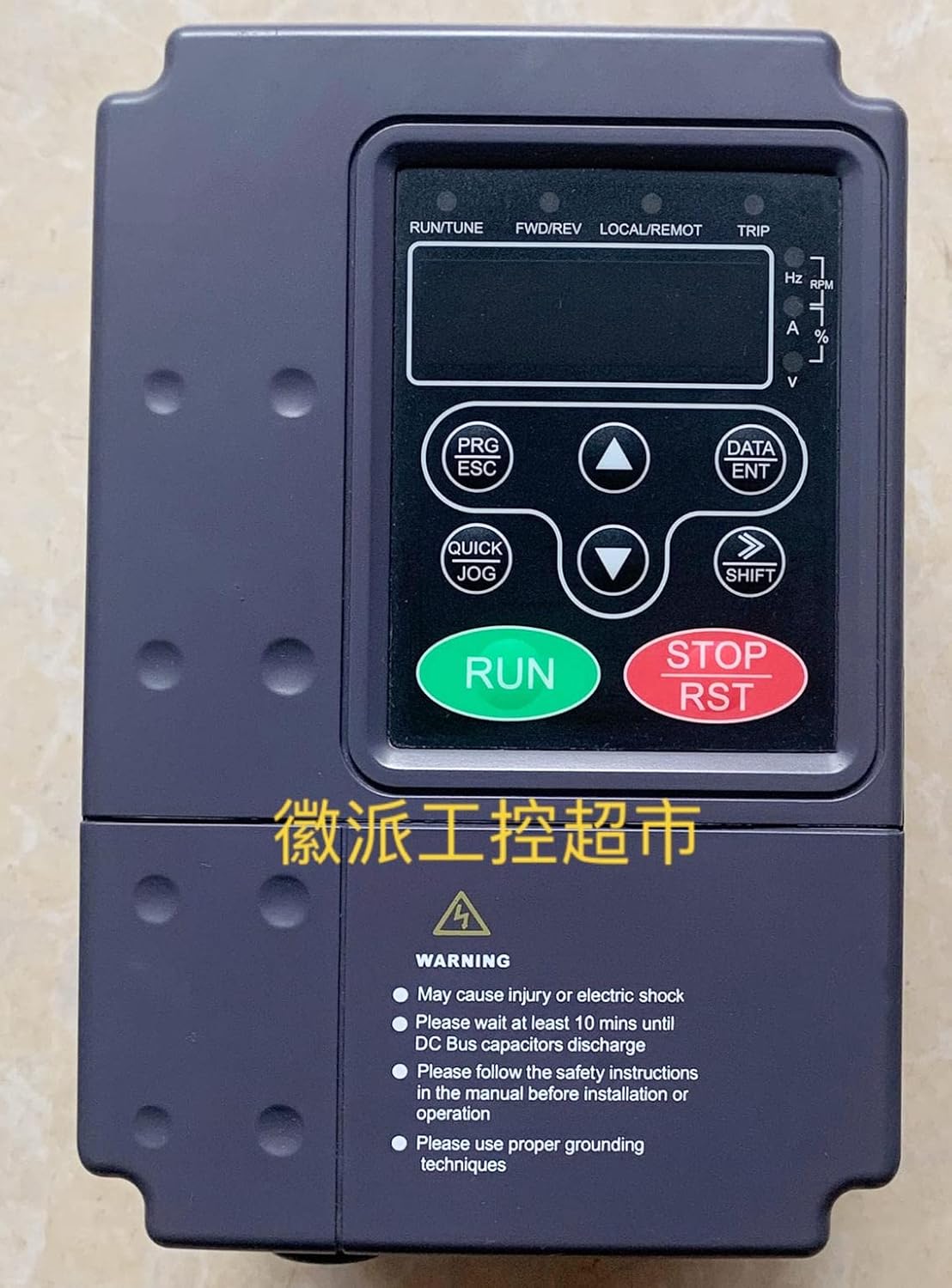
Figure 1: Front view of the CHF100A-1R5G-S2 VFD control panel. This image displays the main operational interface, including the digital display, status indicators, and control buttons for programming and manual operation. Key indicators for frequency (Hz), RPM, current (A), percentage (%), and voltage (V) are visible on the right side of the display. The bottom section includes important safety warnings regarding electric shock, capacitor discharge time, adherence to safety instructions, and proper grounding techniques.
Control Panel Elements:
- Digital Display: Shows operational parameters, frequency, voltage, current, and error codes.
- Status Indicators (LEDs):
- RUN/TUNE: Indicates running status or tuning mode.
- FWD/REV: Indicates forward or reverse direction.
- LOCAL/REMOT: Indicates local (control panel) or remote control mode.
- TRIP: Indicates a fault or trip condition.
- Parameter Indicators: Hz, RPM, A, %, V for displaying specific output values.
- PRG/ESC Button: Enters/exits parameter programming mode or cancels current operation.
- DATA/ENT Button: Confirms data entry or enters sub-menus.
- Up Arrow (▲) Button: Increases parameter values or navigates menus upwards.
- Down Arrow (▼) Button: Decreases parameter values or navigates menus downwards.
- QUICK JOG Button: Initiates a quick jog operation for testing or precise positioning.
- SHIFT Button: Shifts cursor position during parameter editing or changes display mode.
- RUN Button (Green): Starts the motor.
- STOP/RST Button (Red): Stops the motor or resets fault conditions.
4. Setup and Installation
4.1 Mounting
- Mount the VFD vertically on a flat, non-flammable surface.
- Ensure adequate ventilation and clearance around the unit for heat dissipation. Refer to the full installation manual for specific clearance requirements.
- Avoid mounting in areas subject to excessive vibration, dust, or direct sunlight.
4.2 Wiring
All wiring must comply with local and national electrical codes. Use appropriate wire gauges for the input power, motor, and control circuits.
- Power Input: Connect the 220V AC power supply to the designated input terminals (typically R, S, T or L1, L2, L3 for three-phase, or L, N for single-phase).
- Motor Output: Connect the motor leads to the output terminals (U, V, W).
- Grounding: Connect the ground terminal of the VFD to a reliable earth ground. Ensure the motor frame is also properly grounded.
- Control Wiring: Connect external control signals (e.g., start/stop, speed reference, fault relays) to the control terminals as per your application requirements.
5. Operating Instructions
5.1 Basic Operation
- Power On: Apply power to the VFD. The display will illuminate.
- Parameter Setting: Use the PRG/ESC and DATA/ENT buttons along with the Up/Down arrows to set essential parameters such as motor rated frequency, maximum output frequency, acceleration/deceleration times, and control mode. Refer to the detailed parameter list in the complete manual for specific codes.
- Start Motor: Press the RUN button on the control panel or activate the external start command. The RUN/TUNE indicator will light up.
- Adjust Speed: If configured for local control, use the Up/Down arrow buttons to adjust the output frequency and motor speed.
- Stop Motor: Press the STOP/RST button on the control panel or activate the external stop command. The motor will decelerate and stop.
5.2 Advanced Functions
The CHF100A-1R5G-S2 supports various advanced functions including multi-speed operation, PID control, communication interfaces, and fault diagnostics. Configuration of these features requires detailed parameter adjustments, which are covered in the comprehensive product manual.
6. Maintenance
Regular maintenance ensures the longevity and reliable operation of your VFD.
- Cleaning: Periodically clean the VFD's exterior and cooling fins to prevent dust accumulation, which can hinder heat dissipation. Use a soft, dry cloth. Do not use liquids or solvents.
- Inspection: Regularly inspect wiring connections for tightness and signs of wear or damage. Check for any unusual noises or odors during operation.
- Fan Replacement: Cooling fans have a finite lifespan. Consider replacing them after several years of continuous operation, especially in dusty environments.
- Capacitor Check: Electrolytic capacitors have a limited lifespan. If the VFD is operating in high temperatures, their lifespan may be reduced. This typically requires professional inspection.
7. Troubleshooting
This section provides general guidance for common issues. For detailed fault codes and solutions, refer to the complete product manual.
- No Display/Power: Check input power supply and fuses. Ensure connections are secure.
- Motor Not Running: Verify RUN command is active. Check motor wiring. Ensure no fault (TRIP indicator) is present. Check frequency reference setting.
- Overcurrent Trip: May indicate motor overload, short circuit in motor wiring, or incorrect acceleration time. Check motor load and parameters.
- Overvoltage Trip: Often caused by regenerative braking or excessively fast deceleration. Increase deceleration time or add a braking resistor if necessary.
- Undervoltage Trip: Input power supply voltage is too low. Check power source.
- Overheat Trip: VFD is overheating. Check ambient temperature, ensure proper ventilation, and clean cooling fins. Reduce load if possible.
If a fault occurs, note the displayed error code and consult the full manual for specific diagnostic steps. After resolving the issue, press the STOP/RST button to clear the fault.
8. Specifications
| Feature | Specification |
|---|---|
| Model | CHF100A-1R5G-S2 |
| Input Voltage | 220V AC |
| Rated Power | 1.5 KW |
| Rated Current | 14.2 A |
| Manufacturer | Generic |
| ASIN | B0C3BHRSFB |
| First Available Date | April 23, 2023 |
9. Warranty and Support
Specific warranty terms and conditions for the Generic CHF100A-1R5G-S2 Inverter VFD Frequency AC Drive are not provided in this document. Please refer to your purchase documentation or contact the seller for detailed warranty information and technical support.