1. Introduction
This manual provides detailed instructions for the installation, operation, and maintenance of the Generic IPMMB-FM Motherboard. This motherboard is designed for use in H9-1490JP Z75 PC Desktop systems, specifically compatible with models 696399-001 and 696887-002. Please read this manual thoroughly before proceeding with installation to ensure proper setup and safe operation.
2. Safety Information
Always observe the following safety precautions when handling computer components:
- Electrostatic Discharge (ESD) Protection: Always wear an anti-static wrist strap or frequently touch a grounded metal object (like the computer case) before handling the motherboard or any other internal components. ESD can severely damage electronic parts.
- Power Disconnection: Ensure the computer's power supply is unplugged from the wall outlet before installing or removing any components.
- Component Handling: Handle the motherboard by its edges. Avoid touching integrated circuits, pins, or connectors directly.
- Ventilation: Ensure adequate ventilation within the computer case to prevent overheating.
- Tool Usage: Use appropriate tools, such as a Phillips head screwdriver, and avoid excessive force when installing components.
3. Motherboard Layout and Components
Familiarize yourself with the various components and connectors on the IPMMB-FM motherboard.
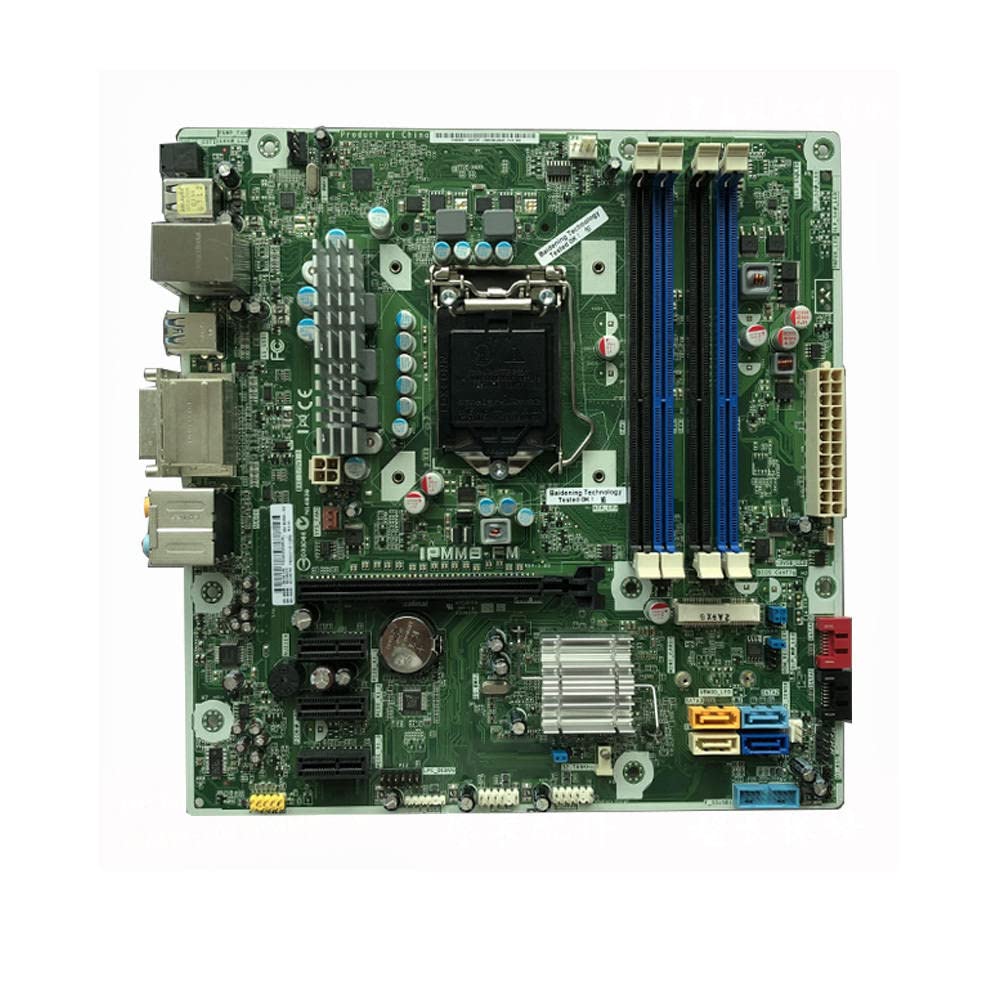
Figure 3.1: Overall view of the IPMMB-FM motherboard, showing the CPU socket, RAM slots, PCIe slots, SATA ports, and various headers.
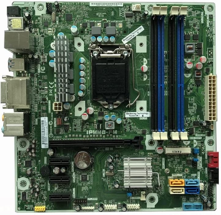
Figure 3.2: This image highlights the CPU socket area, surrounded by power delivery components. To the right, two blue DIMM slots for DDR3 memory are visible, along with the 24-pin ATX power connector at the far right edge.

Figure 3.3: A detailed view showing the CMOS battery (CR2032) for BIOS settings retention. Above it are several PCIe expansion slots, including a full-length PCIe x16 slot and smaller PCIe x1 slots. Below the battery, various headers and capacitors are visible.

Figure 3.4: This section displays the SATA data ports, color-coded for identification (e.g., blue, yellow, orange). These are used for connecting storage devices like hard drives and SSDs. Below them are various front panel headers for USB and system controls.

Figure 3.5: The rear I/O panel connectors are shown, including USB ports (USB 2.0 and USB 3.0), an Ethernet port, DVI video output, and audio jacks for speakers, microphone, and line-in.
4. Setup and Installation
4.1 Pre-installation Checklist
- Anti-static wrist strap.
- Phillips head screwdriver.
- Thermal paste (if installing a new CPU cooler).
- Your CPU, RAM, storage devices, and power supply.
4.2 CPU Installation
- Locate the CPU socket on the motherboard (refer to Figure 3.2).
- Gently push down the load lever and pull it away from the socket to open the CPU retention frame.
- Carefully align the CPU with the socket, matching the gold triangle on the CPU with the triangle on the socket. Do not force the CPU into the socket.
- Lower the retention frame and push the load lever back into its locked position.
- Install the CPU cooler according to its manufacturer's instructions.
4.3 RAM (Memory) Installation
- Locate the two DIMM slots (refer to Figure 3.2).
- Open the clips at both ends of the DIMM slot.
- Align the notch on the RAM module with the key in the DIMM slot.
- Insert the RAM module firmly into the slot until the clips snap into place. Ensure both clips are fully closed.
4.4 Storage Device Installation (SATA)
- Locate the SATA ports on the motherboard (refer to Figure 3.3 and 3.4). The motherboard supports SATA 3.
- Connect one end of a SATA data cable to a SATA port on the motherboard.
- Connect the other end of the SATA data cable to your hard drive or SSD.
- Connect a SATA power cable from your power supply to the storage device.
4.5 Power Supply Connections
- Connect the 24-pin ATX main power connector from your power supply to the corresponding port on the motherboard (refer to Figure 3.2).
- Connect the 4-pin or 8-pin CPU power connector (EPS12V) from your power supply to the CPU power header near the CPU socket.
4.6 Front Panel and I/O Connections
- Connect the front panel headers (Power SW, Reset SW, HDD LED, Power LED) to the corresponding pins on the motherboard (refer to Figure 3.4 for general location). Consult your PC case manual for specific pin assignments.
- Connect front panel USB and audio headers to their respective ports on the motherboard.
- Connect external peripherals (monitor, keyboard, mouse, Ethernet cable) to the rear I/O panel ports (refer to Figure 3.5).
4.7 Expansion Card Installation (PCIe)
- Locate the PCIe slots (refer to Figure 3.3).
- Remove the corresponding expansion slot cover from your PC case.
- Align your expansion card (e.g., graphics card) with the chosen PCIe slot and press down firmly until it is seated correctly.
- Secure the card with a screw or retention clip to the PC case.
5. Operating Instructions
5.1 First Boot
After all components are installed and connected, plug in the power supply and press the power button on your PC case. The system should power on and display the BIOS/UEFI splash screen.
5.2 Accessing BIOS/UEFI
To access the BIOS/UEFI setup utility, repeatedly press the DEL or F2 key immediately after powering on the system. The exact key may vary; refer to the on-screen prompt during boot-up.
5.3 Driver Installation
After installing your operating system, install the necessary drivers for the motherboard's chipset, audio, network, and any other integrated components. These drivers are typically provided by the system manufacturer or can be downloaded from their official website.
6. Maintenance
6.1 Cleaning
Regularly clean the interior of your computer case to prevent dust buildup, which can lead to overheating. Use compressed air to remove dust from fans, heatsinks, and the motherboard surface. Ensure the system is powered off and unplugged before cleaning.
6.2 BIOS Updates
BIOS updates can provide improved compatibility, stability, and new features. Only update the BIOS if necessary and follow the specific instructions provided by the system manufacturer. Incorrect BIOS updates can render the motherboard inoperable.
6.3 CMOS Battery Replacement
The CMOS battery (CR2032, refer to Figure 3.3) powers the BIOS settings and real-time clock. If your system frequently loses time or BIOS settings, the CMOS battery may need replacement. Ensure the system is powered off and unplugged before replacing the battery.
7. Troubleshooting
This section provides solutions to common issues you might encounter.
7.1 No Power
- Check if the power supply is plugged into a working outlet and switched on.
- Ensure all power cables (24-pin ATX, CPU power) are securely connected to the motherboard.
- Verify that the front panel power switch cable is correctly connected to the motherboard header.
7.2 No Display
- Ensure the monitor is connected to the correct video output port (either on the motherboard's I/O panel or a dedicated graphics card).
- Reseat the RAM modules. Try booting with only one RAM module installed.
- Reseat any installed graphics card.
- Clear the CMOS by removing the CMOS battery for 30 seconds (with power unplugged) or using the CMOS clear jumper if available.
7.3 System Instability / Random Restarts
- Check CPU and GPU temperatures to ensure they are not overheating.
- Verify that all components are securely seated.
- Test RAM modules individually or run a memory diagnostic tool.
- Ensure your power supply provides sufficient and stable power to all components.
8. Specifications
Key technical specifications for the IPMMB-FM Motherboard:
| Feature | Description |
|---|---|
| Brand | Generic |
| Model | IPMMB-FM |
| Compatible Devices | Personal Computer (H9-1490JP Z75 PC Desktop) |
| Memory Slots Available | 2 |
| System Bus Standard Supported | SATA 3 |
| ASIN | B0C3BH98FS |
| Date First Available | April 23, 2023 |
9. Warranty and Support
9.1 Return Policy
This product is subject to a 30-day return policy for refund or replacement. Please refer to your purchase documentation for specific terms and conditions.
9.2 Extended Protection Plans
Extended protection plans may be available for purchase separately to cover your product beyond the standard return period. Options may include 3-Year Protection Plan, 4-Year Protection Plan, or a Complete Protect plan. These plans are offered by third-party providers and are not included with the motherboard purchase.
9.3 Technical Support
For technical assistance or further inquiries, please contact the seller or the manufacturer directly through the platform where the product was purchased. Provide your product model (IPMMB-FM) and any relevant order information for faster service.


