X99-BD4
HUANANZHI X99-BD4 Server Mainboard User Manual
Model: X99-BD4 | Brand: Generic
1. Introduction
This user manual provides comprehensive instructions for the installation, operation, and maintenance of the HUANANZHI X99-BD4 Server Mainboard. Designed for server applications, this mainboard supports LGA 2011-3 processors and features a 4-channel memory architecture. Please read this manual thoroughly before proceeding with installation to ensure proper setup and optimal performance.
2. Safety Information
Always observe the following safety precautions when handling the mainboard and other computer components:
- Electrostatic Discharge (ESD) Prevention: Always wear an anti-static wrist strap or frequently touch a grounded metal object before handling the mainboard to prevent ESD damage.
- Power Disconnection: Ensure the power supply is disconnected from the wall outlet before installing or removing any components.
- Component Handling: Handle components by their edges. Avoid touching pins, leads, or circuit paths.
- Ventilation: Ensure adequate ventilation within the computer case to prevent overheating.
- Professional Installation: If you are unsure about any installation steps, seek assistance from a qualified technician.
3. Package Contents
Verify that all items are present in the package. If any item is missing or damaged, contact your retailer.
- HUANANZHI X99-BD4 Server Mainboard
- I/O Shield
- SATA Cables (quantity may vary)
- User Manual (this document)
- Driver CD/USB (if included)
4. Product Overview
The HUANANZHI X99-BD4 mainboard is designed for high-performance server and workstation applications. Below are key components and their locations.

Figure 4.1: Top-down view of the HUANANZHI X99-BD4 Server Mainboard, showing the LGA 2011-3 CPU socket, four DDR4 DIMM slots, multiple PCIe slots, and various headers.

Figure 4.2: Angled view highlighting the CPU socket area, VRM heatsinks, and the layout of the memory and expansion slots.
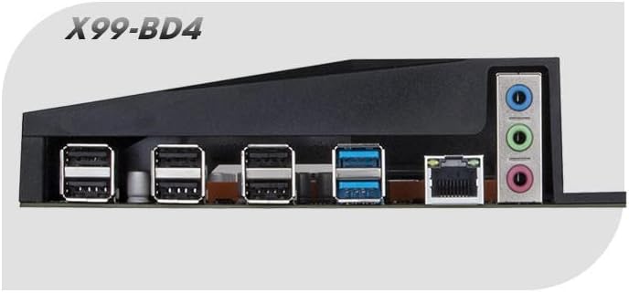
Figure 4.3: Close-up of the rear I/O panel, displaying USB ports, Ethernet port, and audio jacks.
Key Components:
- CPU Socket (LGA 2011-3): Supports Intel Haswell-E, Broadwell-E, and Skylake-E processors.
- DDR4 DIMM Slots (4-Channel): Four slots for DDR4 memory modules, supporting quad-channel configurations.
- PCI Express Slots: Multiple PCIe slots for graphics cards, network cards, and other expansion cards.
- SATA Ports: Connect storage devices such as HDDs and SSDs.
- M.2 Slot: For high-speed NVMe or SATA M.2 SSDs.
- USB Ports: Various USB 2.0 and USB 3.0 ports on the rear I/O panel and internal headers.
- Ethernet Port: For network connectivity.
- Audio Jacks: For audio input and output.
- 24-Pin ATX Power Connector: Main power input for the motherboard.
- 8-Pin EPS Power Connector: Additional power for the CPU.
- Debug LED: A two-digit display that shows POST codes for troubleshooting.
5. Setup and Installation
Follow these steps carefully to install your HUANANZHI X99-BD4 mainboard and its components.
5.1. Preparing the Mainboard
- Place the mainboard on a non-conductive, flat surface (e.g., the anti-static bag it came in).
- Install the CPU:
- Open the CPU socket retention levers.
- Carefully align the CPU with the socket, ensuring the gold triangle on the CPU matches the triangle on the socket.
- Gently lower the CPU into the socket. Do not force it.
- Close the retention levers to secure the CPU.
- Install the CPU Cooler:
- Apply thermal paste to the CPU if not pre-applied on the cooler.
- Mount the CPU cooler according to its manufacturer's instructions.
- Connect the CPU fan cable to the CPU_FAN header on the mainboard.
- Install Memory Modules (RAM):
- Open the clips on both ends of the DIMM slots.
- Align the notch on the DDR4 memory module with the key in the DIMM slot.
- Press down firmly on both ends of the memory module until the clips snap into place. For quad-channel, refer to the mainboard's silkscreen for recommended slot population order.
5.2. Installing the Mainboard into the Chassis
- Install the I/O Shield into the rear opening of your computer case.
- Align the mainboard with the standoffs in the chassis.
- Secure the mainboard with screws, ensuring it is firmly seated.
5.3. Connecting Peripherals and Power
- Connect the 24-pin ATX power cable from the power supply to the mainboard.
- Connect the 8-pin EPS (CPU) power cable from the power supply to the mainboard.
- Install your graphics card (if applicable) into the primary PCIe x16 slot and connect any required PCIe power cables from the power supply.
- Connect SATA data cables from your storage devices (HDDs/SSDs) to the SATA ports on the mainboard. Connect SATA power cables from the power supply to the devices.
- Connect front panel cables (Power SW, Reset SW, HDD LED, Power LED, USB, Audio) to their respective headers on the mainboard. Refer to the mainboard's silkscreen or a detailed diagram for correct pin assignments.
- Connect any additional fans to the fan headers on the mainboard.
6. Operating Instructions
After successful installation, you can proceed with initial boot-up and system configuration.
6.1. Initial Boot-Up
- Ensure all connections are secure.
- Connect your monitor, keyboard, and mouse.
- Connect the power supply to a wall outlet and flip the power switch on the PSU to the 'ON' position.
- Press the power button on your computer case.
- Observe the POST (Power-On Self-Test) process. The debug LED on the mainboard will display codes indicating the boot status.
- Press the designated key (usually DEL or F2) during boot-up to enter the BIOS/UEFI setup utility.
6.2. BIOS/UEFI Setup
The BIOS (Basic Input/Output System) or UEFI (Unified Extensible Firmware Interface) is the firmware that initializes hardware during the boot process. Key settings include:
- Boot Order: Set the priority of boot devices (e.g., USB drive for OS installation, then SSD/HDD).
- Date and Time: Set the system clock.
- CPU Settings: Adjust CPU-related features (e.g., virtualization technology, power management).
- Memory Settings: Configure memory frequency and timings (XMP/DOCP profiles).
- SATA Configuration: Set SATA mode (AHCI is recommended for SSDs).
- Fan Control: Adjust fan speeds based on temperature.
Save changes and exit the BIOS/UEFI to continue with operating system installation.
6.3. Driver Installation
After installing your operating system, install the necessary drivers for the mainboard's components to ensure full functionality and optimal performance. Drivers typically include:
- Chipset Drivers
- LAN (Ethernet) Drivers
- Audio Drivers
- USB Drivers (if specific ones are required)
- SATA/NVMe Drivers
Drivers can usually be found on the manufacturer's website or on the included driver CD/USB.
7. Maintenance
Proper maintenance can extend the lifespan of your mainboard and ensure stable operation.
- Dust Removal: Regularly clean dust from inside your computer case, especially from fans and heatsinks, using compressed air. Ensure the system is powered off and unplugged before cleaning.
- BIOS/UEFI Updates: Periodically check the manufacturer's website for BIOS/UEFI updates. Updates can improve compatibility, stability, and performance. Follow the update instructions carefully to avoid damaging the mainboard.
- Driver Updates: Keep your system drivers updated to ensure compatibility and optimal performance with new software and hardware.
- Environmental Control: Operate the system in a cool, dry, and well-ventilated environment. Avoid extreme temperatures and humidity.
8. Troubleshooting
This section provides solutions to common issues you might encounter.
8.1. Debug LED Codes
The mainboard features a two-digit debug LED display that shows POST (Power-On Self-Test) codes. These codes can help identify the component causing a boot failure. Refer to the mainboard's specific documentation (if available) for a full list of codes. Common codes include:
- 00 / FF: Usually indicates a successful boot or a problem with the CPU/BIOS.
- 20-2F: Memory initialization issues.
- 40-4F: Graphics card issues.
- 50-5F: Storage device issues.
8.2. Common Issues and Solutions
- No Power:
- Check if the power supply is connected to the wall outlet and switched on.
- Ensure the 24-pin ATX and 8-pin EPS power cables are securely connected to the mainboard.
- Verify the front panel power button cable is correctly connected to the mainboard header.
- No Display:
- Ensure the monitor is connected to the graphics card (or integrated graphics, if applicable) and powered on.
- Reseat the graphics card in its PCIe slot.
- Try one RAM stick at a time in different slots to rule out faulty memory.
- Check the debug LED for relevant error codes.
- System Instability / Crashes:
- Check CPU and GPU temperatures. Ensure adequate cooling.
- Verify all power connections are secure.
- Run memory diagnostic tools to check for RAM errors.
- Ensure all drivers are up to date.
- Operating System Not Found:
- Check SATA/NVMe cable connections to storage devices.
- Verify boot order in BIOS/UEFI.
- Ensure the operating system is correctly installed on the drive.
9. Specifications
Detailed technical specifications for the HUANANZHI X99-BD4 Server Mainboard:
| Feature | Specification |
|---|---|
| Brand | Generic |
| Model Name | X99-BD4 |
| CPU Socket | LGA 2011-3 |
| Compatible Processors | Intel Haswell-E, Broadwell-E, Skylake-E |
| Chipset Type | Intel X99 |
| Memory Slots Available | 4 (DDR4, Quad-Channel) |
| Graphics Card Interface | PCI Express |
| Main Power Connector Type | 24-Pin ATX |
| Number of Ports | 20 (various I/O and internal headers) |
| Compatible Devices | Server |
10. Warranty and Support
This product is covered by a standard manufacturer's warranty. For specific warranty terms and conditions, please refer to the documentation provided with your purchase or contact your retailer. For technical support, driver downloads, and BIOS updates, please visit the official HUANANZHI website or contact their customer service.
Date First Available: April 23, 2023
Ask a question about this manual
Ask about setup, troubleshooting, compatibility, parts, safety, or missing instructions. Manuals+ will review the question and use this page’s manual context to help answer it.