1. Introduction
This manual provides essential information for the installation, operation, and maintenance of the Generic S5517G2NR-LE-EFI Server Motherboard. This motherboard is designed for server applications, specifically compatible with systems such as the Xerox C60, C70, Fiery E200-05, and TYAN S5517. Please read this manual thoroughly before proceeding with installation or operation to ensure proper functionality and system stability.
2. Product Overview
The S5517G2NR-LE-EFI is a robust server motherboard engineered for reliable performance in demanding environments. It features an integrated graphics card interface, two memory slots, and supports the SATA 3 system bus standard. The board is designed to accommodate specific server processors and components, providing a stable foundation for your server infrastructure.

Figure 2.1: Top-down view of the Generic S5517G2NR-LE-EFI Server Motherboard. This image provides a general layout of the motherboard, showing the placement of major components such as the CPU socket, memory slots, and various expansion slots.
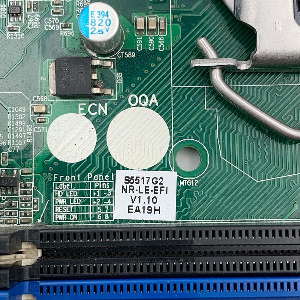
Figure 2.2: A detailed view of the label indicating the model number S5517G2NR-LE-EFI, version V1.10, and other identification codes. This label is essential for verifying the specific motherboard model.
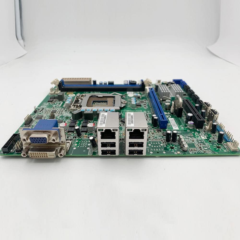
Figure 2.3: This side view illustrates the motherboard's input/output (I/O) panel, featuring VGA and DVI video outputs, dual Ethernet (LAN) ports, and USB ports. These ports are used for connecting peripherals and network cables.
3. Specifications
The following table outlines the key technical specifications for the S5517G2NR-LE-EFI Server Motherboard:
| Feature | Specification |
|---|---|
| Brand | Generic |
| Model Number | S5517G2NR-LE-EFI |
| Manufacturer | Generic |
| Chipset Type | AMD |
| Main Power Connector Type | 24-Pin |
| Graphics Card Interface | Integrated |
| Memory Slots Available | 2 |
| System Bus Standard Supported | SATA 3 |
| ASIN | B0C3BGSC3H |

Figure 3.1: A close-up view of a label confirming the S5517 design and FCC compliance, surrounded by various electronic components. This indicates the board's design origin and regulatory adherence.
4. Setup and Installation
Proper installation is crucial for the stability and performance of your server system. Always ensure you are working in an anti-static environment and handle the motherboard by its edges to prevent damage from electrostatic discharge.
4.1 Pre-Installation Checklist
- Ensure compatibility of all components (CPU, RAM, power supply, chassis).
- Gather necessary tools: Phillips head screwdriver, anti-static wrist strap.
- Read the manuals for your CPU, RAM, and chassis for specific installation instructions.
4.2 Motherboard Installation Steps
- Prepare the Chassis: Install standoffs in your server chassis according to the motherboard's mounting holes.
- Install the CPU: Carefully open the CPU socket lever. Align the CPU with the socket (match the golden triangle/notch) and gently place it into the socket. Close the lever to secure the CPU.
- Install the CPU Cooler: Follow the cooler manufacturer's instructions to install the CPU heatsink and fan assembly. Ensure proper thermal paste application.
- Install RAM: Open the clips on the memory slots. Align the RAM modules with the slots (notch alignment) and press firmly until the clips snap into place. Refer to your system's manual for proper dual-channel configuration if applicable.
- Mount the Motherboard: Carefully place the motherboard into the chassis, aligning the mounting holes with the standoffs. Secure the motherboard with screws.
- Connect Power: Connect the 24-pin main power connector from your power supply to the motherboard. Connect the CPU power connector (typically 4-pin or 8-pin) as well.
- Connect Storage Devices: Connect SATA data cables from your storage drives (HDDs/SSDs) to the SATA 3 ports on the motherboard. Connect power cables from the power supply to the drives.
- Connect Front Panel Cables: Connect the power switch, reset switch, HDD LED, and power LED cables from the chassis front panel to the corresponding pins on the motherboard. Refer to the motherboard's silkscreen labels for correct orientation.
- Install Expansion Cards: Insert any necessary expansion cards (e.g., additional network cards) into the appropriate PCIe slots (PCIe X16, PCIe X8). Secure them with screws.

Figure 4.1: This image displays the back of the server motherboard, featuring the central CPU socket, multiple memory DIMM slots, and the intricate circuit board design. This view is crucial for identifying component placement during installation.
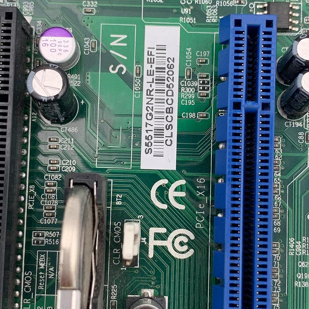
Figure 4.2: This image highlights the PCIe X16 and PCIe X8 expansion slots, along with a serial number barcode. These slots are used for installing expansion cards such as graphics cards or network adapters.
5. Operating Instructions
Once all components are installed and connected, you can proceed with initial system boot-up.
5.1 Initial Boot and BIOS/UEFI Setup
- Power On: Connect the power cord to the power supply and press the power button on your chassis.
- Access BIOS/UEFI: During the initial boot sequence, repeatedly press the designated key (commonly DEL, F2, F10, or F12) to enter the BIOS/UEFI setup utility. The exact key may vary; refer to the on-screen prompts.
- Configure Settings: Within the BIOS/UEFI, configure settings such as boot order, date/time, and enable/disable integrated peripherals as required for your server environment. Save changes and exit.
5.2 Operating System Installation
After configuring the BIOS/UEFI, you can proceed with installing your preferred server operating system. Boot from your installation media (USB drive or optical disc) and follow the on-screen instructions for OS installation.
6. Maintenance
Regular maintenance helps ensure the longevity and stable operation of your server motherboard and system.
- Dust Removal: Periodically clean dust from the motherboard, CPU cooler, and chassis fans using compressed air. Ensure the system is powered off and unplugged before cleaning.
- Cable Management: Ensure all cables are securely connected and properly routed to maintain good airflow within the chassis.
- Firmware Updates: Check the manufacturer's website for BIOS/UEFI firmware updates. Apply updates only if necessary and follow the provided instructions carefully. Incorrect firmware updates can render the motherboard inoperable.
- Environmental Control: Operate the server in a clean, temperature-controlled environment to prevent overheating and component degradation.
7. Troubleshooting
This section provides solutions to common issues you might encounter.
7.1 No Power / No Boot
- Check Power Connections: Ensure the 24-pin main power connector and the CPU power connector are firmly seated. Verify the power supply is switched on and connected to a working outlet.
- Front Panel Connections: Double-check the power switch cable connection to the motherboard.
- Minimal Boot: Disconnect all non-essential components (storage drives, expansion cards) and try booting with only the CPU, one RAM stick, and the CPU cooler.
7.2 No Display Output
- Monitor Connection: Ensure the monitor is properly connected to the motherboard's integrated graphics output (VGA or DVI) and is powered on.
- RAM Seating: Reseat the RAM modules. Faulty or improperly seated RAM can prevent display output.
- BIOS Reset: Try clearing the CMOS (Complementary Metal-Oxide-Semiconductor) by removing the CMOS battery for a few minutes or using the CLR_CMOS jumper if available.
7.3 System Instability / Crashes
- Overheating: Check CPU and system temperatures. Ensure CPU cooler is properly installed and fans are functioning.
- RAM Issues: Run a memory diagnostic tool to check for faulty RAM modules.
- Power Supply: An insufficient or failing power supply can cause instability.
8. Warranty and Support
For warranty information and technical support, please refer to the specific terms provided by your retailer or the manufacturer at the time of purchase. Keep your proof of purchase for any warranty claims. This manual does not constitute a warranty statement.