1. Introduction
This manual provides detailed instructions for the installation, operation, and maintenance of the Generic WS C621E SAGE Motherboard. This motherboard supports 1st and 2nd Generation Intel Xeon Scalable Processors with an LGA3647 socket and features support for 4-way SLI™ / CrossFireX™ technologies. Please read this manual thoroughly before beginning installation to ensure proper setup and to prevent damage to your components.
2. Safety Information
- Always disconnect the power cord from the wall outlet before touching any components.
- Wear an anti-static wrist strap to prevent electrostatic discharge (ESD) damage to components.
- Handle components by their edges, avoiding contact with pins or circuitry.
- Ensure proper ventilation within your PC case to prevent overheating.
- Keep the motherboard away from moisture and extreme temperatures.
3. Package Contents
Verify that all items are present in your motherboard package. If any items are missing or damaged, contact your retailer.
- Generic WS C621E SAGE Motherboard
- SATA Data Cables
- I/O Shield
- User Manual (this document)
- Support DVD/USB drive (containing drivers and utilities)
- SLI/CrossFireX Bridge (if applicable)
4. Setup and Installation
4.1 Motherboard Installation
Carefully align the motherboard with the standoffs in your PC case. Ensure the I/O shield is properly seated in the case opening before securing the motherboard with screws. Do not overtighten the screws.

Figure 4.1: WS C621E SAGE Motherboard installed in a system chassis. This image displays the overall layout of the motherboard within a computer case, including the dual CPU sockets, multiple RAM slots, and various expansion slots, along with connected power supply cables and storage bays.
4.2 CPU Installation (LGA3647)
The WS C621E SAGE motherboard features dual LGA3647 sockets for Intel Xeon Platinum 8100/8200, Gold 6100/6200, and Silver 4100/4200 processors. Follow these steps:
- Open the CPU socket retention mechanism.
- Carefully align the processor with the socket, ensuring the triangular markers match. Do not force the CPU into the socket.
- Close the retention mechanism to secure the CPU.
- Apply thermal paste to the CPU surface.
- Install the CPU cooler according to its manufacturer's instructions. Ensure proper contact and secure mounting.
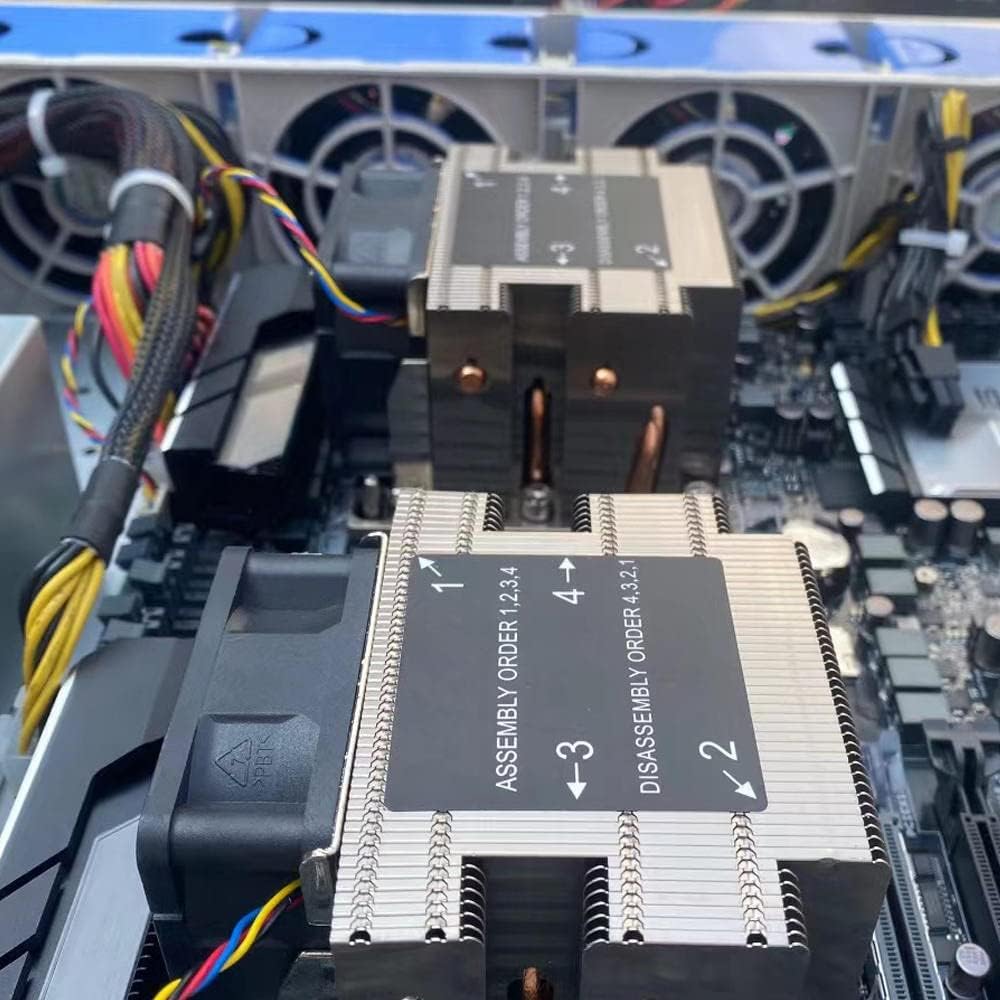
Figure 4.2: Close-up view of the CPU coolers on the WS C621E SAGE motherboard. The image highlights the heatsinks and fans, with labels indicating the recommended assembly order (1, 2, 3, 4) and disassembly order (4, 3, 2, 1) for securing the coolers to the CPU sockets.
4.3 RAM Installation (DDR3)
This motherboard supports DDR3 RAM. Refer to the motherboard manual for specific memory slot population guidelines for optimal performance (e.g., quad-channel configuration).
- Open the clips at both ends of the DIMM slot.
- Align the RAM module with the slot, ensuring the notch on the module matches the key in the slot.
- Press down firmly on both ends of the RAM module until the clips snap into place.
4.4 Storage Device Installation
The motherboard provides 8 SATA 3 ports. Connect your SATA storage devices (HDDs/SSDs) using SATA data cables to these ports. Connect the power cables from your power supply to the devices.
4.5 PCIe Expansion Cards
Install graphics cards or other PCIe expansion cards into the available PCI Express slots. This motherboard supports 4-way SLI™ and CrossFireX™ configurations. Ensure the card is fully seated and secured with the case latch or screw.
4.6 Power Connections
Connect the 24-pin ATX main power connector and the CPU power connectors (e.g., 8-pin EPS12V) from your power supply to the corresponding ports on the motherboard. Ensure all connections are secure.
4.7 Front Panel Connectors
Connect the front panel cables from your PC case (power button, reset button, USB ports, audio jacks, LED indicators) to the corresponding headers on the motherboard. Refer to the motherboard's silkscreen labels for correct pin alignment.
5. Operating Instructions
5.1 First Boot
After completing all hardware installations, connect your monitor, keyboard, and mouse. Power on your system. The system should perform a Power-On Self-Test (POST). If successful, you will see the BIOS/UEFI screen or a prompt to install an operating system.
5.2 BIOS/UEFI Settings
To enter the BIOS/UEFI setup utility, press the designated key (usually DEL or F2) during the POST sequence. Here you can configure boot order, system time, CPU settings, memory timings, and other advanced features. Save changes before exiting.
5.3 Driver Installation
After installing your operating system, install the necessary drivers for the motherboard chipset, LAN, audio, and any other integrated components. These drivers are typically provided on the included support DVD/USB or can be downloaded from the manufacturer's website.
6. Maintenance
- Cleaning: Regularly clean dust from inside your PC case, especially from CPU coolers, fans, and heatsinks, using compressed air. Ensure the system is powered off and unplugged before cleaning.
- BIOS Updates: Periodically check the manufacturer's website for BIOS/UEFI updates. Updates can improve stability, add support for new hardware, or fix bugs. Follow the update instructions carefully to avoid damaging the motherboard.
- Component Checks: Periodically inspect cables for secure connections and check for any signs of physical damage or corrosion on components.
7. Troubleshooting
7.1 Common Issues
- No Power: Ensure the power supply is connected correctly to the motherboard (24-pin and CPU power) and that the power supply switch is on. Check the front panel power button connection.
- No Display/POST: Verify that the CPU, RAM, and graphics card are properly seated. Try booting with only one RAM stick. Check monitor connections.
- System Instability/Crashes: This can be caused by overheating, faulty RAM, or an unstable overclock. Check temperatures, run memory diagnostic tools, and reset BIOS settings to default.
- Operating System Not Booting: Check boot order in BIOS/UEFI. Ensure the storage drive with the OS is detected and functional.
7.2 Diagnostic LEDs/Beep Codes
The motherboard may feature diagnostic LEDs or emit beep codes during POST to indicate specific issues. Refer to the motherboard's specific documentation (if available) for a detailed explanation of these indicators.
8. Specifications
| Feature | Specification |
|---|---|
| Brand | Generic |
| Model Name | WS C621E SAGE |
| CPU Socket | LGA 3647 |
| Compatible Processors | Intel Xeon Platinum 8100/8200, Intel Xeon Gold 6100/6200, Intel Xeon Silver 4100/4200 |
| RAM Memory Technology | DDR3 |
| Chipset Type | WS C621E SAGE |
| Main Power Connector Type | 24-Pin |
| Graphics Card Interface | PCI Express |
| Total SATA Ports | 8 |
| Total PCIe Ports | 8 |
| Compatible Devices | Server, Personal Computer |
9. Warranty and Support
For warranty information and technical support, please refer to the documentation provided by your retailer or the manufacturer's official website. Keep your proof of purchase for warranty claims.


