1. Introduction
This manual provides comprehensive instructions for the installation, operation, and maintenance of the Generic Inspiron 5675 MT DT Desktop Motherboard, model 477DV 7PR60 AM4. Please read this manual thoroughly before proceeding with any installation or operation to ensure proper functionality and safety.
2. Safety Information
Observe the following safety precautions to prevent damage to the motherboard and injury to yourself:
- Always disconnect the power supply from the wall outlet before installing or removing any components.
- Wear an anti-static wrist strap or frequently touch a grounded metal object to discharge static electricity before handling the motherboard or other components.
- Handle the motherboard by its edges to avoid touching sensitive components.
- Ensure proper ventilation within the computer case to prevent overheating.
- Keep the motherboard away from liquids and extreme temperatures.
- If you are unsure about any installation step, consult a qualified technician.
3. Product Overview
The Generic Inspiron 5675 MT DT Desktop Motherboard (477DV 7PR60 AM4) is designed for desktop computer systems, featuring an AM4 CPU socket and support for various internal components. Below is an overview of the motherboard's key features and components.
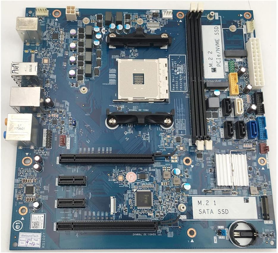
Figure 3.1: Top-down view of the Inspiron 5675 MT DT Desktop Motherboard. This image displays the overall layout, including the AM4 CPU socket, RAM slots, PCIe slots, and various connectors.

Figure 3.2: Another angled top-down view of the motherboard, highlighting the M.2 slots for PCIe/NVMe SSD and SATA SSD, as well as the SATA data ports.

Figure 3.3: Side view of the motherboard, illustrating the various input/output (I/O) ports available, including USB, Ethernet, and audio jacks.

Figure 3.4: Close-up of specific connectors and integrated circuits on the motherboard, showing details of the power connectors and other headers.

Figure 3.5: Detailed view of the rear I/O panel, featuring PS/2 ports, USB ports, Ethernet port, and audio jacks for peripheral connectivity.
Key Components:
- CPU Socket (AM4): For compatible AMD processors.
- DIMM Slots (2): For DDR4 memory modules.
- PCIe Slots: For expansion cards such as graphics cards.
- M.2 Slots: Supports both PCIe/NVMe SSDs and SATA SSDs.
- SATA Ports: For connecting SATA storage devices (HDDs/SSDs).
- I/O Panel: Includes USB ports, Ethernet, audio jacks, and PS/2 ports.
- Power Connectors: 24-pin ATX power connector and 4-pin CPU power connector.
4. Setup and Installation
Follow these steps for proper installation of the motherboard and its components into your computer case.
4.1 Pre-Installation Checks
- Ensure your computer case is compatible with the motherboard's form factor.
- Verify that your CPU, RAM, and other components are compatible with this motherboard. Refer to the specifications section.
- Gather necessary tools: screwdriver, anti-static wrist strap, thermal paste (for CPU).
4.2 Motherboard Installation
- Install the I/O shield into the rear opening of your computer case.
- Carefully place the motherboard into the case, aligning the screw holes with the standoffs.
- Secure the motherboard with screws. Do not overtighten.
4.3 CPU Installation
- Open the CPU socket lever.
- Align the CPU with the socket, ensuring the triangle/arrow on the CPU matches the one on the socket. Gently place the CPU into the socket. Do not force it.
- Close the CPU socket lever to secure the CPU.
- Apply thermal paste to the CPU (if not pre-applied on the cooler) and install the CPU cooler according to its manufacturer's instructions.
4.4 RAM Installation
- Open the clips on both ends of the DIMM slots.
- Align the notch on the RAM module with the notch in the DIMM slot.
- Press down firmly on both ends of the RAM module until the clips snap into place.
4.5 Storage Device Installation (M.2 / SATA)
- M.2 SSD: Insert the M.2 SSD into the appropriate slot at an angle, then gently push it down and secure it with the provided screw.
- SATA Devices: Connect one end of a SATA data cable to a SATA port on the motherboard and the other end to your HDD/SSD. Connect a SATA power cable from your power supply to the HDD/SSD.
4.6 Power Supply Connections
- Connect the 24-pin ATX power cable from your power supply to the main power connector on the motherboard.
- Connect the 4-pin CPU power cable to the CPU power connector near the CPU socket.
4.7 Front Panel and Peripheral Connections
- Connect the front panel headers (power switch, reset switch, HDD LED, power LED) to the corresponding pins on the motherboard. Refer to your case manual for specific pin assignments.
- Connect USB, audio, and other front panel cables to their respective headers.
- Install any PCIe expansion cards (e.g., graphics card) into the appropriate PCIe slots and secure them.
5. Operating Instructions
After successful installation, follow these steps to power on your system and install an operating system.
5.1 Initial Boot-Up
- Ensure all components are securely connected and the power supply is switched on.
- Press the power button on your computer case.
- The system should power on, and you should see a display on your monitor. If not, refer to the Troubleshooting section.
5.2 BIOS/UEFI Setup
The BIOS (Basic Input/Output System) or UEFI (Unified Extensible Firmware Interface) is the firmware that initializes hardware during the boot process. To enter BIOS/UEFI setup:
- During the initial boot screen, repeatedly press the designated key (commonly Del, F2, F10, or F12). The exact key may vary; check the on-screen prompt.
- Within the BIOS/UEFI, you can configure boot order, system time, fan speeds, and other hardware settings.
- Save changes and exit to continue booting.
5.3 Operating System Installation
To install an operating system (e.g., Windows, Linux):
- Prepare a bootable USB drive or DVD with your desired operating system.
- Enter BIOS/UEFI setup and set the boot device priority to your USB drive or DVD.
- Save and exit. The system will boot from your installation media.
- Follow the on-screen instructions to install the operating system on your storage device.
- After installation, install necessary drivers for the motherboard chipset, graphics card, audio, and network.
6. Maintenance
Regular maintenance helps ensure the longevity and optimal performance of your motherboard and system.
- Dust Removal: Periodically clean dust from inside your computer case using compressed air. Ensure the system is powered off and unplugged. Hold fan blades to prevent them from spinning during cleaning.
- BIOS/UEFI Updates: Check the manufacturer's website for BIOS/UEFI updates. Updates can improve compatibility, stability, and performance. Follow the update instructions carefully to avoid system damage.
- Driver Updates: Keep your system drivers (chipset, graphics, audio, network) updated to ensure optimal performance and compatibility.
- Component Checks: Occasionally check all cable connections (power, data) to ensure they are secure.
7. Troubleshooting
This section addresses common issues you might encounter and provides basic troubleshooting steps.
7.1 No Power / No Boot
- Check Power Connections: Ensure the 24-pin ATX and 4-pin CPU power cables are securely connected to the motherboard and power supply.
- Power Supply Switch: Verify the power supply's main switch is in the 'ON' position.
- Front Panel Connectors: Double-check that the power switch cable from the case is correctly connected to the motherboard's front panel header.
- Test Power Supply: If possible, test the power supply with another system or use a power supply tester.
7.2 No Display Output
- Monitor Connection: Ensure the monitor is properly connected to the graphics card (or integrated graphics port) and is powered on.
- Graphics Card: If using a dedicated graphics card, ensure it is fully seated in its PCIe slot and any required PCIe power cables are connected.
- RAM: Reseat the RAM modules. Try booting with only one RAM module installed in different slots.
- Clear CMOS: Refer to the motherboard manual (or look for a jumper/button on the board) to clear the CMOS settings, which can resolve display issues caused by incorrect BIOS settings.
7.3 System Instability / Crashes
- Overheating: Check CPU and GPU temperatures. Ensure CPU cooler is properly installed and fans are spinning. Clean dust from heatsinks.
- RAM Issues: Run a memory diagnostic tool (e.g., Windows Memory Diagnostic, MemTest86) to check for faulty RAM.
- Driver Issues: Ensure all drivers are up-to-date and correctly installed. Reinstall problematic drivers if necessary.
- Power Supply: An insufficient or failing power supply can cause instability.
8. Specifications
Below are the technical specifications for the Generic Inspiron 5675 MT DT Desktop Motherboard (477DV 7PR60 AM4).
| Feature | Specification |
|---|---|
| Brand | Generic |
| CPU Socket | Socket AM4 |
| Compatible Devices | Personal Computer |
| Compatible Processors | Intel Core 2 DUO (Note: This specification appears to be a mismatch with AM4 socket. Please verify CPU compatibility with the manufacturer.) |
| Memory Slots Available | 2 |
| S/PDIF Connector Type | Optical |
| System Bus Standard Supported | SATA 3 |
| Date First Available | April 23, 2023 |
Note: The listed "Compatible Processors: Intel Core 2 DUO" appears to be an inconsistency with the "CPU Socket: Socket AM4" specification. Socket AM4 is for AMD Ryzen processors. Please consult the manufacturer or product documentation for accurate CPU compatibility.
9. Warranty and Support
This product is manufactured by Generic. For specific warranty information, please refer to the documentation provided with your purchase or contact the seller directly.
- Return Policy: A 30-day return/replacement policy is typically offered by the seller. Please check your purchase details for exact terms.
- Technical Support: For technical assistance, please contact the seller or manufacturer.


