1. Introduction
This manual provides comprehensive instructions for the installation, operation, and maintenance of the Generic XC3-32RT-E Programmable Logic Controller (PLC). The XC3-32RT-E is a robust AC220V controller module featuring 18 digital inputs (DI) and 14 digital outputs (DO) with a mixed relay and transistor output configuration. It is designed for industrial automation applications requiring reliable and precise control.
Please read this manual thoroughly before operating the device to ensure safe and efficient use.
2. Safety Information
Always observe the following safety precautions to prevent personal injury and damage to the equipment:
- Ensure the power supply is disconnected before performing any wiring or maintenance.
- Only qualified personnel should install, operate, and maintain this device.
- Verify all wiring connections are correct and secure to prevent short circuits or malfunctions.
- Do not expose the PLC to excessive moisture, dust, or extreme temperatures.
- Use appropriate personal protective equipment (PPE) when working with electrical systems.
- Ground the PLC properly according to local electrical codes.
3. Product Overview
The XC3-32RT-E PLC is a compact and powerful controller designed for various industrial control tasks. It integrates digital inputs and mixed digital outputs (relay and transistor) to provide flexible control capabilities.
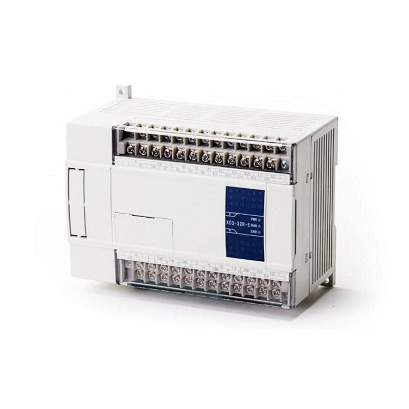
Figure 3.1: Front view of the XC3-32RT-E PLC module, showing input and output terminal blocks and status indicators.
Key Features:
- AC220V Power Supply: Directly compatible with standard industrial power.
- 18 Digital Inputs (DI): For connecting sensors, switches, and other input devices.
- 14 Digital Outputs (DO): Mixed relay and transistor outputs for controlling actuators, motors, and other output devices.
- Compact Design: Space-saving form factor for easy integration into control panels.
- Status Indicators: LEDs for power (PWR), run (RUN), and error (ERR) status.
4. Specifications
| Parameter | Value |
|---|---|
| Model | XC3-32RT-E |
| Brand | Generic |
| Power Supply | AC220V |
| Digital Inputs (DI) | 18 points |
| Digital Outputs (DO) | 14 points (Relay and Transistor Mixed) |
| ASIN | B0C3BG6J2K |
| First Available Date | April 23, 2023 |
5. Setup and Installation
5.1 Mounting
The XC3-32RT-E PLC is designed for DIN rail mounting. Ensure adequate ventilation space around the module to prevent overheating. Mount the PLC in a stable environment free from excessive vibration.
5.2 Wiring
Refer to the wiring diagrams provided with your specific application for detailed connections. Below are general guidelines:
- Power Supply: Connect the AC220V power supply to the designated power terminals. Ensure correct polarity if applicable and proper grounding.
- Digital Inputs: Connect input devices (e.g., push buttons, limit switches, sensors) to the DI terminals. Observe input voltage specifications.
- Digital Outputs: Connect output devices (e.g., relays, contactors, indicator lights) to the DO terminals. Note that outputs are mixed relay and transistor types; ensure the load current and voltage are within the specified limits for each output type.
- Communication Ports: If applicable, connect programming cables or communication modules to the designated communication ports (e.g., RS232, RS485) for programming and monitoring.
Important: All wiring should be done with the power supply disconnected. Double-check all connections before applying power.
6. Operating Instructions
6.1 Powering On
After completing all wiring and ensuring safety, apply AC220V power to the PLC. The PWR indicator LED should illuminate, indicating successful power-up.
6.2 Programming
The XC3-32RT-E PLC is programmed using dedicated PLC programming software (typically provided by the manufacturer or compatible third-party software). Connect the PLC to a computer via the appropriate communication cable.
- Install the PLC programming software on your computer.
- Launch the software and establish communication with the PLC.
- Create or load your ladder logic program or other supported programming language.
- Download the program to the PLC.
- Switch the PLC to RUN mode (either via software command or a physical switch if available). The RUN indicator LED should illuminate.
6.3 Monitoring and Debugging
The programming software allows for real-time monitoring of input/output status, internal registers, and program execution. Use these features to debug your program and verify system operation.
7. Maintenance
The XC3-32RT-E PLC is designed for low maintenance. However, regular checks can extend its lifespan and ensure reliable operation.
- Environmental Check: Periodically inspect the operating environment to ensure it remains within specified temperature and humidity ranges. Keep the area free of dust and corrosive gases.
- Connection Check: Routinely check all wiring connections for tightness and signs of corrosion. Loose connections can lead to intermittent operation or failure.
- Cleaning: If necessary, gently clean the exterior of the PLC with a soft, dry cloth. Do not use solvents or abrasive cleaners. Ensure power is off before cleaning.
- Firmware Updates: Check the manufacturer's website periodically for any available firmware updates that may improve performance or address known issues. Follow update instructions carefully.
8. Troubleshooting
This section provides solutions to common issues you might encounter with the XC3-32RT-E PLC.
| Problem | Possible Cause | Solution |
|---|---|---|
| PLC does not power on (PWR LED off) | No power supply; incorrect wiring; faulty power supply. | Check AC220V power connection; verify wiring; test power supply. |
| RUN LED is off, ERR LED is on | Program error; hardware fault; communication issue. | Check program logic; restart PLC; consult programming software for error codes; contact support if persistent. |
| Inputs not responding | Sensor/switch fault; incorrect input wiring; input not configured in program. | Test input device; verify input wiring; check PLC program for input assignment. |
| Outputs not activating | Actuator fault; incorrect output wiring; output not triggered by program; overloaded output. | Test output device; verify output wiring; check program logic; ensure load current is within limits. |
| Cannot connect to PLC via software | Incorrect communication settings; faulty cable; driver issues. | Verify COM port and baud rate settings; try a different cable; reinstall communication drivers. |
If the problem persists after attempting these solutions, please contact technical support.
9. Warranty and Support
9.1 Warranty Information
This product is typically covered by a standard manufacturer's warranty against defects in materials and workmanship. Please refer to your purchase documentation or the seller's terms and conditions for specific warranty duration and coverage details. Keep your proof of purchase for warranty claims.
9.2 Technical Support
For technical assistance, programming queries, or advanced troubleshooting, please contact the seller or manufacturer's support team. Have your product model number (XC3-32RT-E) and purchase details ready when contacting support.
Note: No official product videos were provided for this model.


