1. Introduction
This manual provides essential information for the safe and effective operation, installation, and maintenance of the KEYENCE IL-1000 Laser Amplifier. Please read this manual thoroughly before using the product to ensure proper functionality and to prevent potential hazards.
The KEYENCE IL-1000 is a high-precision laser amplifier designed for industrial applications, offering accurate measurement capabilities and robust environmental resistance. It is a main unit designed for DIN-rail mounting and is compatible with various sensor heads.
2. Product Overview

Figure 2.1: KEYENCE IL-1000 Laser Amplifier in its original packaging with manual. The product code 23500KO #9S911828 is visible on the box.
The IL-1000 is a compact laser amplifier unit, designed for easy integration into industrial control systems. It features a digital display for precise readings and multiple input/output options for versatile control.
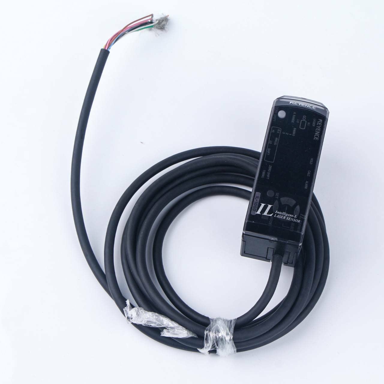
Figure 2.2: The KEYENCE IL-1000 Laser Amplifier unit with its integrated multi-wire cable. This cable provides connections for power and various signals.
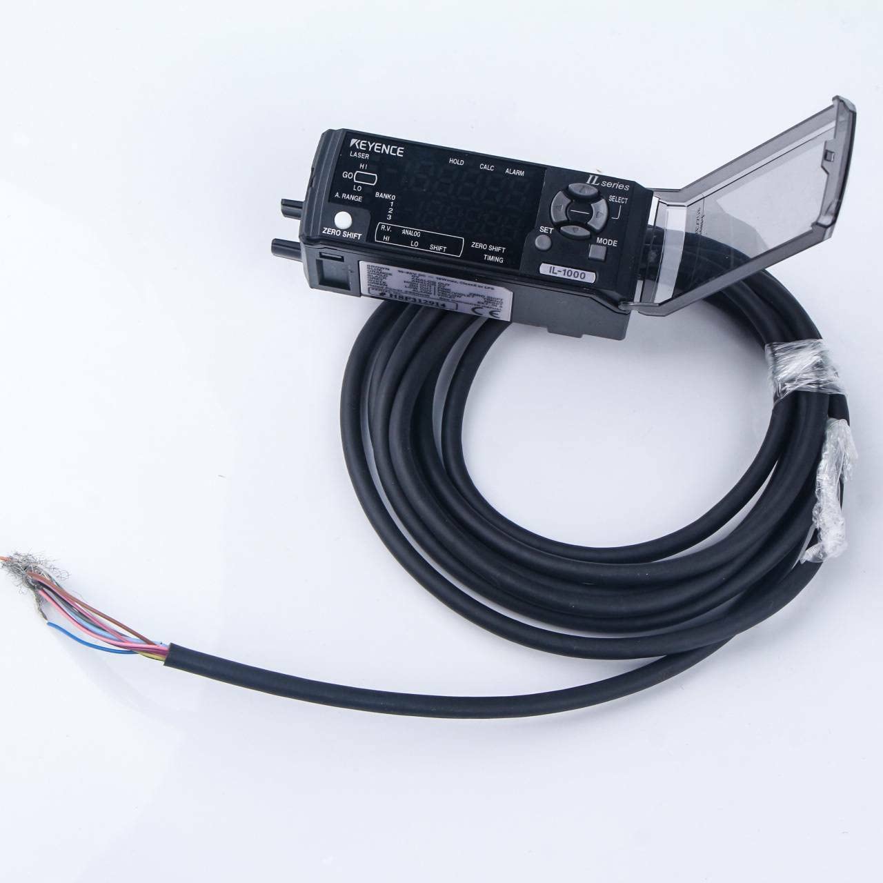
Figure 2.3: The KEYENCE IL-1000 unit with its transparent protective cover opened, revealing the control buttons and display. This cover protects the interface from environmental factors.
3. Setup and Installation
The IL-1000 is designed for DIN-rail mounting, allowing for secure and organized installation within control cabinets. Ensure the power supply meets the specified requirements before connecting the unit.
3.1 Mounting
- Locate a suitable DIN-rail within your control panel.
- Align the IL-1000 unit with the DIN-rail and press firmly until it clicks into place.
- Verify that the unit is securely fastened and does not wobble.
3.2 Wiring
The IL-1000 features a multi-wire cable for power and signal connections. Refer to the wiring diagram on the product label for correct connections.
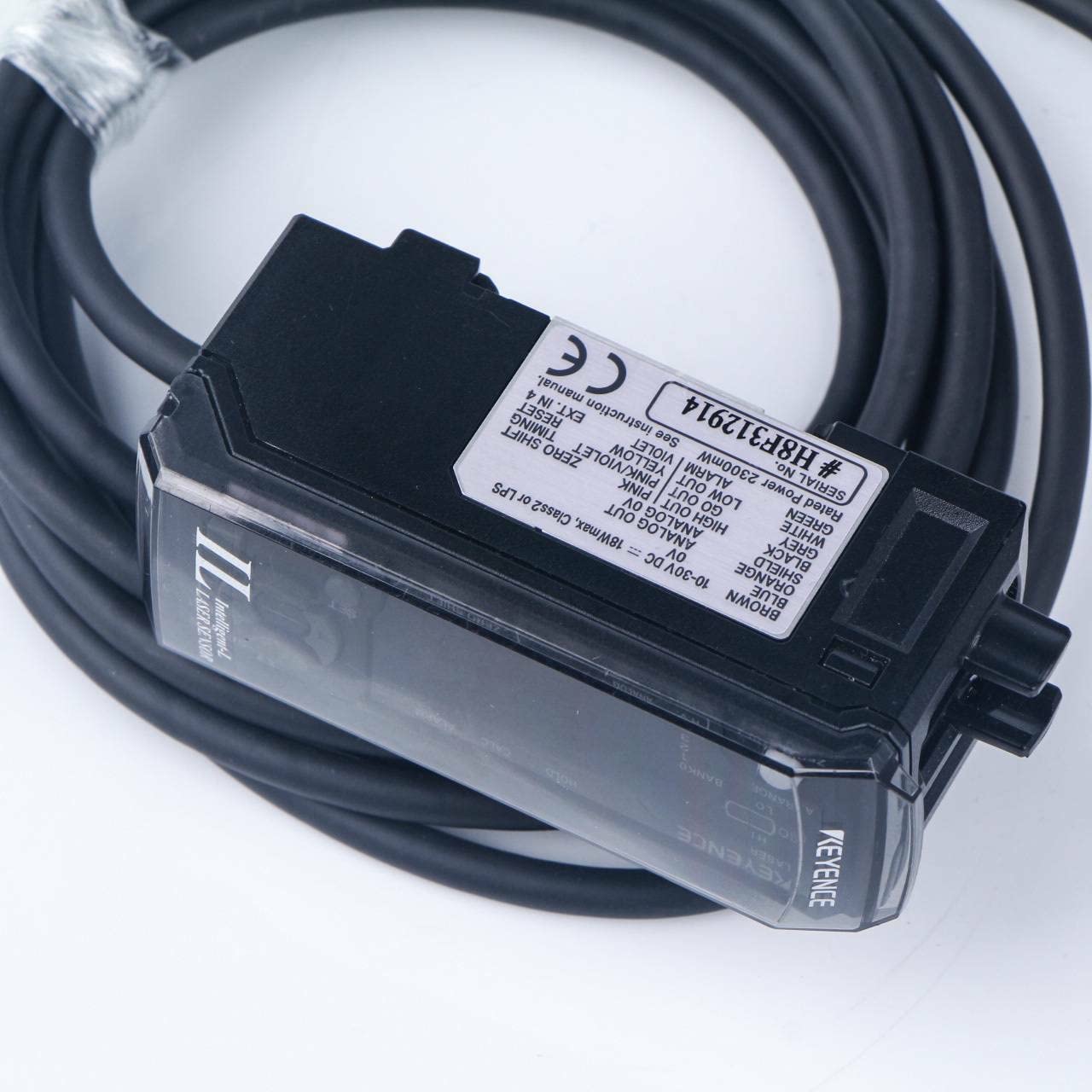
Figure 3.1: Detailed view of the product label on the KEYENCE IL-1000, displaying power requirements (10-30V DC), output types, and the serial number #H8BP312914. This label also provides a wiring guide.
- Power Supply: Connect to a 10 to 30 VDC power source. Ensure the power supply has a ripple (P-P) of 10% or less and is Class 2 compliant.
- Analog Voltage Output: Connect for ±5 V, 1 to 5 V, or 0 to 5 V output. Output impedance is 100 Ω.
- Analog Current Output: Connect for 4 to 20 mA output. Maximum load resistance is 350 Ω.
- Control Inputs: Bank switch, Zero-shift, Stop emission, Timing, and Reset inputs are non-voltage inputs.
- Control Outputs: Judgement and Alarm outputs are open collector outputs (NPN, PNP changeover possible).
4. Operating Instructions
The IL-1000 features an intuitive interface for configuration and monitoring. The display provides real-time measurement data, and the control buttons allow for parameter adjustments.
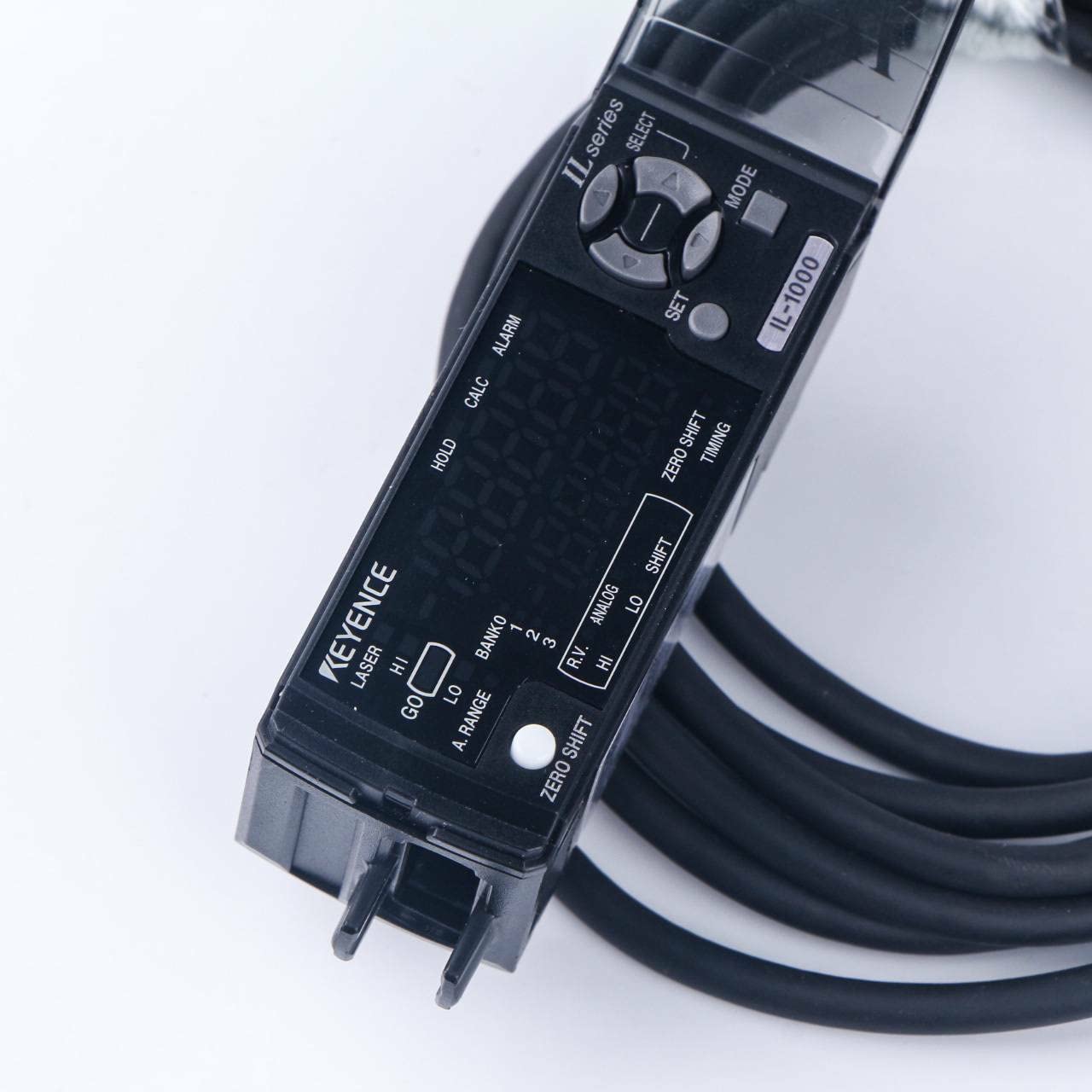
Figure 4.1: The digital display and control buttons (SELECT, MODE, SET) on the KEYENCE IL-1000. Indicators for laser status, bank selection, and output levels are also visible.
4.1 Display Functions
- Minimum Displayable Unit:
- IL-030: 1 µm
- IL-065/IL-100: 2 µm
- IL-300: 10 µm
- IL-600: 50 µm
- IL-2000: 100 µm
- Display Range:
- IL-030/IL-065/IL-100: ±99.999 mm to ±99 mm (4 levels selectable)
- IL-300/IL-600: ±999.99 mm to ±999 mm (3 levels selectable)
- IL-2000: ±9999.9 mm to ±9999 mm (2 levels selectable)
- Display Rate: Approximately 10 times/sec.
4.2 Control Inputs
The following inputs are available for external control:
- Bank Switch Input: For switching between different bank settings.
- Zero-shift Input: To reset the measurement to zero.
- Stop Emission Input: To halt laser emission.
- Timing Input: For synchronization with external events.
- Reset Input: To reset the unit or specific parameters.
4.3 Control Outputs
The IL-1000 provides the following outputs:
- Judgement Output: Indicates if the measurement is within the set limits (N.O., N.C. changeover possible).
- Alarm Output: Signals an error or abnormal condition (N.C.).
5. Maintenance
Regular maintenance ensures the longevity and accuracy of your KEYENCE IL-1000 Laser Amplifier.
5.1 Cleaning
- Wipe the unit with a soft, dry cloth.
- Do not use abrasive cleaners or solvents, as they may damage the polycarbonate case or key tops.
- Ensure the display and sensor window (if applicable) are free from dust and debris for accurate readings.
5.2 Environmental Considerations
The IL-1000 is designed with specific environmental resistance:
- Pollution Degree: 2
- Ambient Temperature: -10 to +50 °C (14 to 122 °F). Avoid condensation or freezing.
- Relative Humidity: 35 to 85 % RH. Avoid condensation.
- Vibration Resistance: 10 to 55 Hz, Double amplitude 1.5 mm (0.06"), 2 hours in each of the X, Y, and Z directions.
6. Troubleshooting
This section provides guidance for common issues you might encounter with the IL-1000. For problems not listed here, please contact technical support.
6.1 Common Issues
| Problem | Possible Cause | Solution |
|---|---|---|
| No power/Display off | Incorrect power supply voltage or connection. | Verify power supply is within 10-30 VDC and connections are secure. Check for blown fuses in the power circuit. |
| Inaccurate readings | Sensor head not properly connected or dirty. Environmental interference. | Ensure sensor head is securely connected. Clean the sensor head and amplifier display. Check for strong electromagnetic interference. |
| Outputs not functioning | Incorrect wiring or output settings. | Review wiring diagram for correct output connections. Check output settings in the amplifier's configuration. |
7. Specifications
Detailed technical specifications for the KEYENCE IL-1000 Laser Amplifier are provided below:
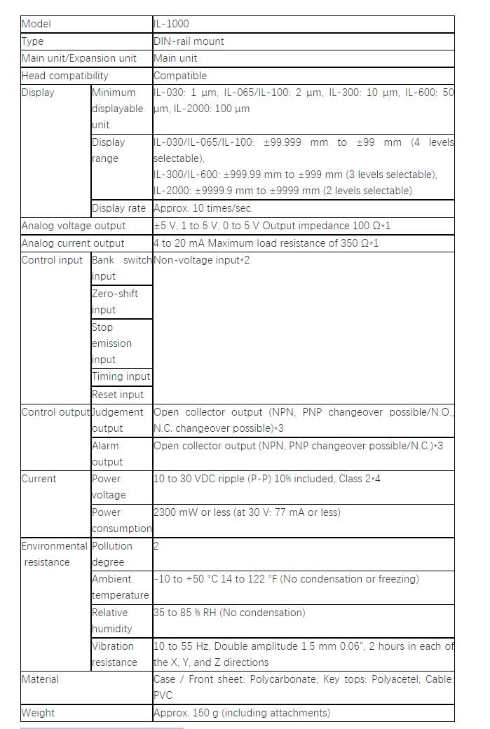
Figure 7.1: A comprehensive table outlining the technical specifications of the KEYENCE IL-1000, including display units, output types, power requirements, environmental resistance, and material composition.
| Parameter | Description/Value |
|---|---|
| Model | IL-1000 |
| Type | DIN-rail mount |
| Main unit/Expansion unit | Main unit |
| Head compatibility | Compatible |
| Minimum displayable unit | IL-030: 1 µm, IL-065/IL-100: 2 µm, IL-300: 10 µm, IL-600: 50 µm, IL-2000: 100 µm |
| Display range | IL-030/IL-065/IL-100: ±99.999 mm to ±99 mm (4 levels selectable) IL-300/IL-600: ±999.99 mm to ±999 mm (3 levels selectable) IL-2000: ±9999.9 mm to ±9999 mm (2 levels selectable) |
| Display rate | Approx. 10 times/sec. |
| Analog voltage output | ±5 V, 1 to 5 V, 0 to 5 V Output impedance 100 Ω |
| Analog current output | 4 to 20 mA Maximum load resistance of 350 Ω |
| Control input | Bank switch input, Zero-shift input, Stop emission input, Timing input, Reset input (all non-voltage inputs) |
| Control output | Judgement output (Open collector NPN, PNP changeover possible/N.O., N.C. changeover possible) Alarm output (Open collector NPN, PNP changeover possible/N.C.) |
| Power voltage | 10 to 30 VDC ripple (P-P) 10% included, Class 2 |
| Power consumption | 2300 mW or less (at 30 V: 77 mA or less) |
| Pollution degree | 2 |
| Ambient temperature | -10 to +50 °C (14 to 122 °F) (No condensation or freezing) |
| Relative humidity | 35 to 85 % RH (No condensation) |
| Vibration resistance | 10 to 55 Hz, Double amplitude 1.5 mm (0.06"), 2 hours in each of the X, Y, and Z directions |
| Material | Case / Front sheet: Polycarbonate; Key tops: Polyacetel; Cable: PVC |
| Weight | Approx. 150 g (including attachments) |
8. Warranty and Support
For warranty information or technical support regarding your KEYENCE IL-1000 Laser Amplifier, please contact the seller or manufacturer directly. Keep your purchase receipt and product serial number (#H8BP312914) readily available when seeking support.
You can find more information about Vanky Industry products on their Amazon store page.