1. Introduction
This manual provides essential information for the safe and effective use of the KEYENCE LR-ZB250AP CMOS Distance Sensor. Please read this manual thoroughly before installation and operation to ensure correct usage and to prevent potential hazards or damage to the product.
The LR-ZB250AP is a distance-based CMOS sensor designed for industrial applications, featuring a PNP output and a 2-meter cable connection. It offers reliable detection over a range of 35 to 250 mm.
2. Safety Information
Observe the following safety precautions to prevent injury to personnel and damage to the equipment.
- Electrical Safety: Ensure power is disconnected before wiring or performing any maintenance. Incorrect wiring can lead to electric shock or fire.
- Operating Environment: Do not use the sensor in environments with flammable or explosive gases.
- Proper Installation: Mount the sensor securely according to the instructions to prevent it from falling or causing injury.
- Power Supply: Use only the specified power supply voltage (10 to 30 VDC). Exceeding this range may damage the sensor.
- Laser Safety: This device uses a Class 1 laser product. Avoid direct exposure to the laser beam.
3. Product Overview
The KEYENCE LR-ZB250AP is a compact, rectangular CMOS distance sensor. It is equipped with a 3-digit 7-segment display for indicators and offers selectable response times.

Figure 1: KEYENCE LR-ZB250AP CMOS Distance Sensor in its original packaging.
Key Features:
- Distance-based Detection: Detectable range of 35 to 250 mm (1.38" to 9.84").
- PNP Output: Open collector control output.
- Selectable Response Time: 1.5 ms / 10 ms / 50 ms.
- Integrated Indicators: 3-digit 7-segment display (red), output indicator (yellow), DATUM indicator (orange), 1 spot indicator (green).
- Timer Function: OFF/ON delay, OFF delay, One-shot.
- Robust Design: IP68, IP69K, NEMA 4X, 6P, 13 enclosure ratings.
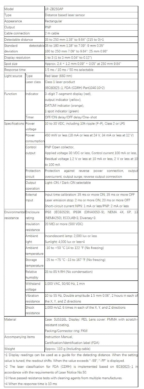
Figure 2: Close-up view of the LR-ZB250AP sensor unit.
4. Setup and Installation
4.1 Mounting
The LR-ZB250AP sensor is designed for flange mounting. Ensure the mounting surface is stable and free from vibration. Secure the sensor firmly using appropriate fasteners.
4.2 Wiring
Connect the sensor to the power supply and control system according to the following specifications. Always ensure power is OFF before making any connections.
- Power Voltage: 10 to 30 VDC (including 10% ripple P-P), Class 2 or LPS.
- Power Consumption: 450 mW or less (18 mA or less at 24 V, 34 mA or less at 12 V).
- Control Output: PNP Open collector, Applied voltage 30 VDC or less, Control current 100 mA or less, Residual voltage 1.2 V or less at 10 mA or less, 2 V or less at 10 to 100 mA.
- Protection Circuit: Protection against reverse power connection, output overcurrent, output surge, reverse output connection.
The sensor comes with a 2-meter cable for connection. Refer to the wiring diagram provided with the product for specific pin assignments.
5. Operating Instructions
5.1 Basic Operation
Once powered, the sensor will initiate. The 3-digit 7-segment display will show detection values or settings. The output indicator (yellow) illuminates when the output is active.
5.2 Output Operation Selection
The sensor supports both Light-ON and Dark-ON output operations. This setting determines whether the output is active when light is detected (Light-ON) or when light is interrupted (Dark-ON). Consult the detailed product manual for instructions on how to switch between these modes.
5.3 Timer Functions
The LR-ZB250AP includes various timer functions:
- OFF/ON Delay: Delays both the turn-off and turn-on of the output.
- OFF Delay: Delays the turn-off of the output.
- One-shot: Provides a momentary output pulse.
These timer settings can be configured via the sensor's interface. Refer to the full product documentation for detailed programming steps.
6. Maintenance
Regular maintenance ensures optimal performance and longevity of the sensor.
- Cleaning: Periodically clean the sensor lens and housing with a soft, dry cloth. For stubborn dirt, use a mild, non-abrasive cleaner. Avoid harsh chemicals that could damage the housing or lens.
- Inspection: Regularly check the cable for any signs of damage, fraying, or loose connections. Ensure the sensor is securely mounted.
- Environmental Conditions: Verify that the operating environment remains within the specified temperature and humidity ranges to prevent sensor malfunction.
7. Troubleshooting
If the sensor is not functioning as expected, consider the following common issues and solutions:
- No Power/Indicator Off:
- Check power supply connections and voltage.
- Ensure the power supply is within the 10-30 VDC range.
- Inconsistent Detection:
- Clean the sensor lens.
- Verify the target is within the detectable distance range (35-250 mm).
- Check for excessive ambient light interference (Sunlight: 4,000 lux or less; Incandescent lamp: 2,000 lux or less).
- Adjust the sensor's position or angle relative to the target.
- Output Not Activating:
- Confirm the output operation mode (Light-ON/Dark-ON) is correctly set for your application.
- Check wiring for the control output.
- Ensure the target is properly detected by observing the output indicator.
For persistent issues, consult the full product manual or contact technical support.
8. Specifications
Detailed technical specifications for the KEYENCE LR-ZB250AP CMOS Distance Sensor are provided below.

Figure 3: Detailed specifications table for the LR-ZB250AP sensor.
| Category | Specification |
|---|---|
| Model | LR-ZB250AP |
| Type | Distance based sensor |
| Appearance | Rectangular |
| Output | PNP |
| Cable connection | 2 m cable |
| Detectable distance | 35 to 250 mm (1.38" to 9.84") |
| Standard detectable deviation | 35 to 180 mm (1.38" to 7.09"): 9 mm (0.35"); 180 to 250 mm (7.09" to 9.84"): 25 mm (0.98") |
| Display resolution | 1 to 3 (1 to 3 mm / 0.04" to 0.12") |
| Spot size | Approx. 2.4 × 1.2 mm (0.09" × 0.05") at 250 mm (9.84") |
| Response time | 1.5 ms / 10 ms / 50 ms selectable |
| Light source | Red laser (680 nm), Class 1 laser product (IEC60825-1, FDA (CDRH) Part1040.10+2) |
| Function - Indicator | 3-digit 7-segment display (red), output indicator (yellow), DATUM indicator (orange), 1 spot indicator (green) |
| Function - Timer | OFF/ON delay / OFF delay / One-shot |
| Power voltage | 10 to 30 VDC, including 10% ripple (P-P), Class 2 or LPS |
| Power consumption | 450 mW or less (18 mA or less at 24 V, 34 mA or less at 12 V) |
| Control output | PNP Open collector, Applied voltage 30 VDC or less, Control current 100 mA or less, Residual voltage 1.2 V or less at 10 mA or less, 2 V or less at 10 to 100 mA |
| Protection circuit | Protection against reverse power connection, output overcurrent, output surge, reverse output connection |
| Output operation | Light-ON / Dark-ON selectable |
| External input | Input time calibration: 35 ms or more ON, 35 ms or more OFF; Emission stop: 2 ms or more ON, 20 ms or more OFF; Short-circuit current NPN: 1 mA or less / PNP: 2 mA or less |
| Enclosure rating | IP68 (IEC60529), IP69K (DIN40050-9), NEMA 4X, 6P, 13 (NEMA250), ECOLAB, Diversey |
| Insulation resistance | 20 MΩ or more (500 VDC) |
| Ambient light | Incandescent lamp: 2,000 lux or less; Sunlight: 4,000 lux or less |
| Ambient temperature | -10 to +50 °C (14 to 122 °F) (No freezing) |
| Storage temperature | -25 to +75 °C (-13 to 167 °F) (No freezing) |
| Relative humidity | 35 to 85 % RH (No condensation) |
| Withstand voltage | 1,000 VAC, 50/60 Hz, 1 min |
| Vibration resistance | 10 to 55 Hz, Double amplitude 1.5 mm (0.06"), 2 hours in each of the X, Y, and Z directions |
| Shock resistance | 1,000 m/s², 6 times in each of the X, Y, and Z directions |
| Material | Case: SUS316L, Display: PES, Lens cover: PMMA with scratch-resistant coating, Packing/Connector ring: FKM |
| Weight | Approx. 110 g (Including cable) |
9. Warranty and Support
For warranty information, please refer to the terms and conditions provided by the seller, Vanky Industry, or contact KEYENCE directly. For technical support or further inquiries, please reach out to your product supplier.