
1. Introduction
The UNI-T UT60S is a smart, true RMS digital multimeter designed for accurate and reliable electrical measurements. Featuring 9999 counts, this device can measure AC/DC voltage, AC/DC current, resistance, diode, capacitance, temperature, and frequency. Its fully automatic anti-burn intelligent design helps prevent operational errors and device damage, making it suitable for both professional technicians and everyday users.

Figure 1: Front view of the UNI-T UT60S Digital Multimeter.
2. Safety Information
Always adhere to safety precautions when using the multimeter. Failure to do so may result in electric shock, injury, or damage to the meter or equipment under test.
- Read the Manual: Before use, thoroughly read and understand all instructions and safety warnings in this manual.
- Rated Voltage: Do not apply more than the rated voltage, as marked on the meter, between terminals or between any terminal and earth ground. The UT60S is capable of withstanding a maximum overvoltage impulse of 1000V.
- Inspect Before Use: Before each use, inspect the meter, test leads, and accessories for any damage. Do not use if damaged.
- Proper Terminals: Ensure test leads are connected to the correct input terminals for the measurement function selected.
- Circuit De-energization: Always de-energize the circuit and discharge all high-voltage capacitors before performing resistance, continuity, diode, or capacitance measurements.
- Live Circuit Work: When working on live circuits, work alone as little as possible, and ensure another person is present to provide assistance if needed.
- Overcurrent Protection: The meter features overcurrent alarms and protection functions. Do not exceed the maximum current ratings for the input terminals.
- Environmental Conditions: Use the meter only as specified in this manual. Do not use the meter in explosive gas, vapor, or dusty environments.
- Personal Protective Equipment: Always wear appropriate personal protective equipment (PPE), such as safety glasses and insulated gloves, when working with electrical circuits.
3. Product Features
The UNI-T UT60S Digital Multimeter offers a range of features for versatile and safe electrical testing:
- 9999 Counts Display: Provides high-resolution measurements for precision.
- True RMS Measurement: Ensures accurate readings for non-sinusoidal waveforms.
- Fully Automatic Anti-Burn Design: Intelligent protection against operational errors and potential device damage.
- Wide Measurement Capabilities: Measures AC/DC voltage (up to 1000V), AC/DC current, resistance, diode, capacitance, temperature, and frequency.
- Large LCD Screen with Dual Display: Allows simultaneous display of AC voltage and frequency, enhancing readability.
- Full Button Design: Offers intuitive control and automatic recognition of current input jacks.
- Fast ADC (Analog to Digital Converter): Provides rapid measurement updates (3 times/second).
- Misoperation Protection: Capable of withstanding a maximum overvoltage impulse of 1000V, with overvoltage and overcurrent alarms.
- NCV (Non-Contact Voltage) Function: Detects AC voltage without physical contact, featuring audible and visual alarms for safety.
- Automatic Power Saving: Low power consumption (7mA during operation, 5uA in sleep state) and automatic backlight display in dark environments, extending battery life. Automatic shut-down feature.

Figure 2: The UT60S display with 9999 counts for precise readings.
4. What's in the Box
Upon opening the package, you should find the following items:
- UNI-T UT60S Digital Multimeter
- Thermocouple (for temperature measurements)
- Multimeter Test Leads (red and black)
- 1.5V AAA Batteries (pre-installed or included separately)

Figure 3: Contents of the UNI-T UT60S package, including the multimeter, test leads, and thermocouple.
5. Setup
5.1. Battery Installation
The UT60S typically uses 1.5V AAA batteries. To install or replace batteries:
- Ensure the multimeter is powered off and test leads are disconnected.
- Locate the battery compartment on the back of the meter.
- Use a screwdriver to open the battery compartment cover.
- Insert the AAA batteries, observing correct polarity (+ and -).
- Replace the battery compartment cover and secure it with the screw.
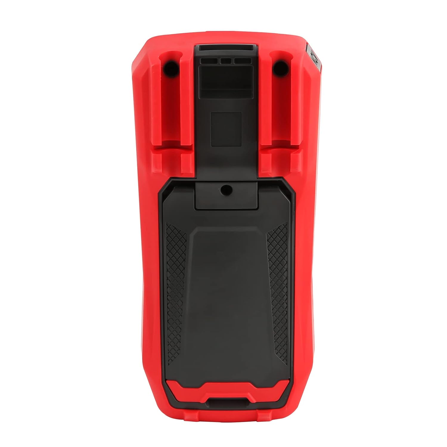
Figure 4: Rear view of the UT60S, indicating the battery compartment location.
5.2. Connecting Test Leads
Connect the test leads to the appropriate input terminals:
- The black test lead (common) should always be connected to the COM terminal.
- For voltage, resistance, capacitance, frequency, diode, and continuity measurements, connect the red test lead to the VΩHzCAP terminal.
- For current measurements (mA/A), connect the red test lead to the mA/A terminal.
- For microampere current measurements (μA), connect the red test lead to the μA terminal.

Figure 5: Input terminals of the UT60S for connecting test leads.
6. Operating Instructions
The UT60S features a full button design for selecting measurement functions. The meter's intelligent anti-burn design automatically recognizes the input jack and selected function.
6.1. Power On/Off
Press the POWER button to turn the meter on or off. The meter will automatically shut down after a period of inactivity to save battery life.
6.2. Auto Mode
In Auto mode, the meter automatically identifies the measurement type (voltage, resistance, continuity) and selects the appropriate range. This simplifies operation for general troubleshooting.
6.3. Measuring AC/DC Voltage
To measure voltage:
- Connect the black test lead to the COM terminal and the red test lead to the VΩHzCAP terminal.
- Press the V~ / Hz button to select AC voltage measurement, or the V= / NCV button for DC voltage. The meter may automatically select the correct mode in Auto range.
- Connect the test probes across the circuit or component to be measured.
- Read the voltage value on the display. For AC voltage, the frequency may also be displayed simultaneously.

Figure 6: Measuring AC voltage and frequency with the UT60S.
6.4. Measuring AC/DC Current
To measure current:
- IMPORTANT: To measure current, the meter must be connected in series with the circuit. Always turn off power to the circuit before connecting the meter.
- Connect the black test lead to the COM terminal.
- For current up to 10A, connect the red test lead to the mA/A terminal. For microampere current, connect to the μA terminal.
- Press the ACA/DCA button to select AC or DC current measurement.
- Break the circuit and connect the test leads in series with the load.
- Apply power to the circuit and read the current value on the display.
6.5. Measuring Resistance, Diode, and Continuity
To measure resistance, diode, or continuity:
- Ensure the circuit is de-energized and capacitors are discharged.
- Connect the black test lead to the COM terminal and the red test lead to the VΩHzCAP terminal.
- Press the Ω→+ button to cycle through resistance, diode, and continuity functions.
- Connect the test probes across the component.
- Read the measurement. For continuity, an audible buzzer will sound if continuity is detected.
6.6. Measuring Capacitance
To measure capacitance:
- Ensure the capacitor is fully discharged before testing.
- Connect the black test lead to the COM terminal and the red test lead to the VΩHzCAP terminal.
- Press the mV~°C°F button to select temperature measurement.
- Connect the test probes across the capacitor terminals.
- Read the capacitance value on the display.

Figure 7: The UT60S performing a capacitance measurement.
6.7. Measuring Temperature
To measure temperature:
- Connect the thermocouple to the appropriate input terminals (usually the VΩHzCAP and COM terminals, or dedicated temperature inputs if available).
- Press the mV~°C°F button to select temperature measurement.
- Place the thermocouple probe at the point where temperature needs to be measured.
- Read the temperature value on the display in Celsius or Fahrenheit.
6.8. NCV (Non-Contact Voltage) Function
The NCV function allows detection of AC voltage without direct contact with conductors.
- Press the V= / NCV button to activate the NCV function.
- Move the top of the meter close to the conductor or outlet.
- The meter will provide an audible alarm and visual indication (flashing light) if AC voltage is detected. The intensity of the alarm and light may vary with voltage strength.

Figure 8: Using the NCV function to detect live AC voltage.
6.9. Data Hold
Press the HOLD button to freeze the current reading on the display. Press it again to release the hold function.
6.10. Range Selection
While the meter typically operates in Auto range, you can manually select a range by pressing the RANGE button. This can be useful for specific applications or to speed up measurements in stable conditions. Press and hold the RANGE button to return to Auto range.
6.11. USB Communication (if applicable)
The UT60S series may support USB communication for data logging and analysis on a computer. If your model includes this feature, connect the meter to your computer using the provided USB cable and install the UNI-T software. Refer to the software manual for detailed instructions.
Video 1: Demonstration of features like NCV, LoZ, and USB communication on a UNI-T UT161 series multimeter. The UT60S shares similar functionalities.
7. Maintenance
7.1. Cleaning
Wipe the meter's case with a damp cloth and mild detergent. Do not use abrasives or solvents. Ensure the meter is completely dry before use.
7.2. Battery Replacement
Replace batteries when the low battery indicator appears on the display. Refer to Section 5.1 for battery installation instructions.
7.3. Fuse Replacement
If the current measurement function stops working, the fuse may need replacement. Refer to the full user manual for specific fuse ratings and replacement procedures. Always use fuses with the specified voltage and current ratings.
8. Troubleshooting
If you encounter issues with your UNI-T UT60S, try the following basic troubleshooting steps:
- No Display/Power On: Check battery installation and ensure batteries are not depleted. Replace if necessary.
- Incorrect Readings: Verify that the test leads are correctly connected to the appropriate terminals for the selected function. Ensure the function dial is set correctly. Check for damaged test leads.
- Current Measurement Not Working: Check the fuse. If blown, replace it with a fuse of the correct rating. Ensure the meter is connected in series with the circuit.
- "OL" or Overload Indication: This indicates that the measured value is outside the selected range or the maximum capability of the meter. Try selecting a higher range (if in manual range mode) or ensure the component is within the meter's specifications.
- NCV Not Detecting: Ensure the NCV function is activated and the meter is brought close enough to the AC voltage source.
For more complex issues, refer to the detailed troubleshooting section in the complete user manual or contact UNI-T customer support.
9. Specifications
Key specifications for the UNI-T UT60S Digital Multimeter:
| Feature | Specification |
|---|---|
| Display Count | 9999 |
| True RMS | Yes |
| AC/DC Voltage | Up to 1000V |
| AC/DC Current | Up to 10A (mA/A terminals), Up to 1000μA (μA terminal) |
| Resistance | 0.1Ω - 40MΩ |
| Capacitance | 1nF - 4000μF |
| Temperature | Yes (with thermocouple) |
| Frequency | Yes |
| Diode Test | Yes |
| Continuity Test | Yes |
| NCV (Non-Contact Voltage) | Yes |
| Power Source | Battery Powered (1.5V AAA batteries) |
| Item Weight | 370 Grams |
| Safety Compliance | UL 61010-1, IEC 61010-2-030, CAT III 1000V, CAT II 600V |
10. Warranty and Support
UNI-T provides customer support for their products. If you encounter any problems during use, please contact UNI-T customer service directly via email. They offer 7/24 1-to-1 user support to address your concerns promptly.
For specific warranty details, please refer to the warranty card included with your product or visit the official UNI-T website.


