Introduction
This manual provides essential information for the safe and effective use of the Generic BL4266 24V Brushless Motor. This motor features a strong magnetic, 9-pole inner rotor design with double ball bearings for enhanced performance and durability. It operates at 24V and includes red, black, and white output wires for connection.
Safety Information
Please read and understand all safety instructions before operating the motor. Failure to follow these instructions may result in electric shock, fire, or serious injury.
- Electrical Safety: Ensure all connections are secure and insulated. Do not operate the motor with damaged wiring.
- Voltage: Use only a 24V power supply. Exceeding the rated voltage can damage the motor.
- Heat: Motors can generate heat during operation. Avoid touching the motor directly after prolonged use. Ensure adequate ventilation.
- Moving Parts: Keep hands, hair, and loose clothing away from rotating parts during operation.
- Environment: Do not expose the motor to water, excessive dust, or corrosive environments.
- Professional Use: This product is intended for users who possess the necessary technical knowledge for its application. Technical support is not provided.
Product Overview
The BL4266 is a robust 24V brushless DC motor designed for various applications. It features a compact design with a 9-pole inner rotor and double ball bearings for smooth and efficient operation.
Motor Components
- Motor Body: Cylindrical housing containing the stator and rotor.
- Output Shaft: The rotating shaft for power transmission.
- Wiring: Red, black, and white wires for power and control.
- Internal Circuitry: Integrated control board for brushless motor operation.
Product Images
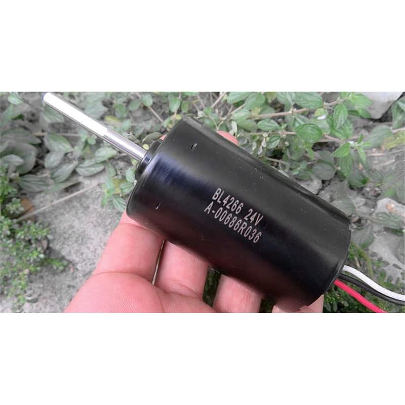
Figure 1: General view of the BL4266 24V Brushless Motor. This image shows the overall appearance of the motor, highlighting its compact cylindrical design and the output shaft.
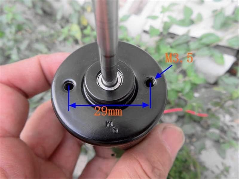
Figure 2: Front view of the BL4266 motor detailing mounting dimensions. This image indicates a mounting hole spacing of 29mm and M3.5 screw size for attachment.
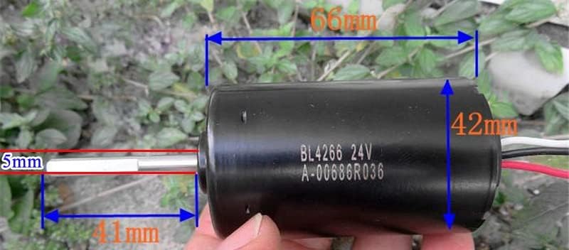
Figure 3: Side view of the BL4266 motor showing overall dimensions. The motor body length is approximately 66mm, diameter 42mm, shaft diameter 5mm, and exposed shaft length 41mm.

Figure 4: Top view of the internal circuit board of the BL4266 motor. This shows various electronic components, including capacitors and integrated circuits, responsible for motor control.
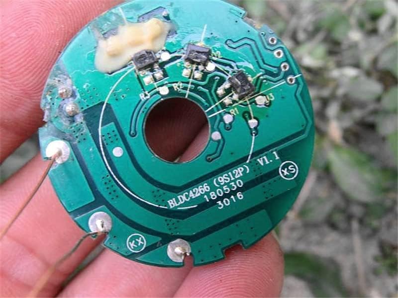
Figure 5: Bottom view of the internal circuit board of the BL4266 motor. This perspective reveals additional traces and components on the reverse side of the control board.

Figure 6: Multiple BL4266 motors shown in their original packaging. This image provides a view of how the motors are typically supplied.
Specifications
| Feature | Specification |
|---|---|
| Model | BL4266 |
| Operating Voltage | 24V |
| Motor Type | Brushless DC Motor (BLDC) |
| Rotor Type | 9-Pole Inner Rotor |
| Bearings | Double Ball Bearings |
| Output Wires | Red, Black, White |
| Weight | Approximately 365g |
| Motor Body Length | 66mm (approx.) |
| Motor Body Diameter | 42mm (approx.) |
| Shaft Diameter | 5mm (approx.) |
| Exposed Shaft Length | 41mm (approx.) |
| Mounting Hole Spacing | 29mm (approx.) |
| Mounting Screw Size | M3.5 (approx.) |
Setup and Installation
Proper installation is crucial for the safe and efficient operation of the BL4266 motor. This motor requires an external brushless motor controller (ESC) for operation, which is not included.
Mounting the Motor
- Identify a suitable mounting surface that can securely hold the motor and withstand any operational vibrations.
- Align the motor's mounting holes with the pre-drilled holes on your mounting surface. Refer to Figure 2 for mounting dimensions (29mm spacing, M3.5 screws).
- Secure the motor using appropriate M3.5 screws. Do not overtighten, as this may damage the motor housing.
Wiring Connections
The BL4266 motor comes with three output wires: Red, Black, and White. These wires are typically connected to a compatible 24V brushless motor controller (ESC).
- Red Wire: Typically positive power input from the ESC.
- Black Wire: Typically negative power input from the ESC.
- White Wire: Typically a signal or control wire from the ESC. The exact function may vary depending on the ESC model. Consult your ESC manual for specific wiring diagrams.
Important: Ensure correct polarity and secure connections to prevent damage to the motor or ESC. Incorrect wiring can lead to motor malfunction or permanent damage.
Operating Instructions
Once the motor is securely mounted and correctly wired to a compatible 24V brushless motor controller (ESC) and power supply, follow these general steps for operation:
- Power On: Connect the 24V power supply to the ESC.
- Controller Setup: Ensure your ESC is properly configured for a 9-pole brushless motor, if applicable.
- Initiate Operation: Use the control input of your ESC (e.g., throttle signal from a microcontroller or remote control) to start and control the motor speed.
- Monitor Performance: Observe the motor for any unusual noises, excessive heat, or vibrations during initial operation. If any anomalies are detected, immediately power off and inspect the setup.
- Power Off: Disconnect the power supply from the ESC when the motor is not in use.
Note: The specific operating procedures will largely depend on the brushless motor controller (ESC) used with this motor. Always refer to the ESC's instruction manual for detailed operational guidelines.
Maintenance
The BL4266 brushless motor is designed for low maintenance. However, periodic checks can help ensure its longevity and optimal performance.
- Cleaning: Keep the motor free from dust, dirt, and debris. Use a soft, dry cloth or compressed air for cleaning. Avoid using liquids.
- Inspections: Regularly check for any signs of physical damage, loose connections, or worn wires.
- Bearings: The double ball bearings are typically sealed and require no lubrication under normal operating conditions. If unusual noise or resistance is detected, the bearings may need inspection by a qualified technician.
- Storage: Store the motor in a dry, clean environment away from extreme temperatures and humidity when not in use.
Troubleshooting
This section provides basic troubleshooting steps for common issues. As technical support is not provided for this product, advanced diagnostics may require professional assistance.
| Problem | Possible Cause | Solution |
|---|---|---|
| Motor does not start or rotate. | No power to ESC/motor; Incorrect wiring; Faulty ESC; Motor damage. | Check power supply and connections. Verify wiring to ESC. Test ESC with another motor if possible. Inspect motor for visible damage. |
| Motor runs intermittently or stutters. | Loose connections; ESC timing issues; Overheating. | Secure all connections. Consult ESC manual for timing adjustments. Ensure adequate cooling. |
| Motor is excessively hot. | Overload; Insufficient cooling; Incorrect ESC settings. | Reduce load on the motor. Improve ventilation. Check ESC settings (e.g., current limits). |
| Unusual noise or vibration. | Loose mounting; Damaged bearings; Obstruction. | Check motor mounting screws. Inspect shaft and bearings for damage. Remove any obstructions. |
Warranty and Support
This product is sold without explicit warranty information provided by the manufacturer. As stated in the product description, technical support for its use is not provided. Users are expected to have the necessary technical knowledge for integration and operation.
For any issues, please refer to the troubleshooting section of this manual or consult with a qualified professional if you lack the expertise to diagnose and resolve problems.