1. Introduction
The SATMW PN103 Digital Clamp Meter is a professional-grade multimeter designed for accurate and reliable electrical measurements. This device features a 6000-count display, True RMS capability, and auto-ranging for ease of use. It can measure AC/DC current, AC/DC voltage, resistance, capacitance, frequency, and temperature, along with diode and continuity tests. Its robust design makes it suitable for a wide range of applications, including household electrical work, automotive diagnostics, and industrial electrical problem-solving.
This manual provides essential information for the safe and effective operation, maintenance, and troubleshooting of your PN103 Digital Clamp Meter. Please read it thoroughly before use.
2. Safety Information
To ensure safe operation and avoid personal injury or damage to the meter, observe the following safety precautions:
- Always ensure the rotary switch is set to the correct measurement range before connecting the test leads to a circuit.
- Do not apply voltage or current that exceeds the maximum specified limits for the meter. The maximum voltage between the measurement terminal and ground is 700V DC or 600V AC.
- The meter features a double-insulated design to minimize the risk of electric shock. However, always exercise caution when working with live circuits.
- Before replacing batteries or fuses, ensure the meter is turned off and all test leads are disconnected from the circuit.
- Do not use the meter if it appears damaged or if the casing is open.
- Keep fingers behind the finger guards on the test leads during measurements.
- The device is rated for CAT III 600V. Adhere to safety standards for the environment you are working in.
3. Product Overview
The PN103 Digital Clamp Meter consists of a clamp jaw for non-contact current measurement, a rotary switch for function selection, a digital display, and input jacks for test leads.
3.1 Components
- Clamp Jaw: Used for non-contact AC/DC current measurement.
- Rotary Switch: Selects measurement functions (Voltage, Current, Resistance, etc.) and turns the meter ON/OFF.
- LCD Display: Shows measurement readings, units, and various indicators. Maximum display value is 6000 counts.
- Function Buttons:
- HOLD: Freezes the current display reading.
- SELECT: Toggles between functions within a rotary switch position (e.g., AC/DC, Diode/Continuity) and activates the backlight.
- REL: Relative measurement mode.
- Input Jacks: For connecting test leads (COM and INPUT).
- Flashlight: Integrated light for illuminating the measurement area.
3.2 Display Features
- 6000 Counts: High-resolution display for precise readings.
- "OL" Indicator: Appears when the measured value exceeds the selected range.
- Low Voltage Symbol: Indicates low battery power.
- Backlight: Improves visibility in dimly lit environments. Activated via the SELECT button.
- Automatic Shut-down: The meter will automatically power off after approximately 15 minutes of inactivity to conserve battery life.

Figure 3.1: Dimensions of the PN103 Digital Clamp Meter. The meter measures approximately 184.5mm (7.26 inches) in length and 68mm (2.67 inches) in width.

Figure 3.2: The PN103 features a backlit screen for night vision, a screen lighting function, and an automatic shut-down feature after 15 minutes of inactivity to prolong battery life.
4. Setup
4.1 Battery Installation
The PN103 Digital Clamp Meter requires two 1.5V batteries (not included) for operation.
- Ensure the meter is turned OFF and all test leads are disconnected.
- Locate the battery compartment cover on the back of the meter.
- Use a screwdriver to loosen the screw(s) securing the battery cover.
- Remove the cover and insert two 1.5V batteries, observing the correct polarity (+ and -).
- Replace the battery cover and tighten the screw(s) securely.
5. Operating Instructions
Before taking any measurements, ensure the meter is properly set up and the batteries are installed. Always select the appropriate function using the rotary switch.
5.1 AC/DC Current Measurement (Clamp)
- Turn the rotary switch to the AC or DC current position (e.g., 60A or 600A range).
- Open the clamp jaw by pressing the trigger.
- Place the clamp jaw around a single conductor wire. Ensure the wire is centered within the jaw.
- Close the clamp jaw. The current reading will appear on the display.
- Important: For accurate readings, only clamp around a single wire. Clamping around multiple wires will result in an incorrect reading or zero if currents cancel out.
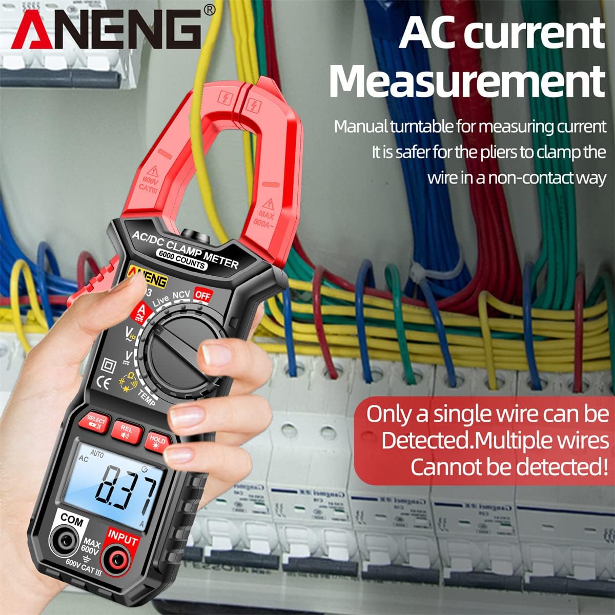
Figure 5.1: Measuring AC current using the clamp jaw. Ensure only a single wire is detected for accurate measurement.

Figure 5.2: The PN103 can measure DC current in applications such as automobiles. Adjust the rotary switch to the DC current range and clamp around the wire.
5.2 AC/DC Voltage Measurement
- Insert the black test lead into the COM jack and the red test lead into the INPUT jack.
- Turn the rotary switch to the V~ (AC Voltage) or V- (DC Voltage) position. The meter will auto-range.
- Connect the test probes across the circuit or component you wish to measure.
- Read the voltage value on the display.

Figure 5.3: The PN103 can measure AC current (left) by clamping a single wire, and AC voltage (right) by connecting test leads to the circuit.
5.3 Resistance Measurement
- Ensure the circuit is de-energized before measuring resistance.
- Insert the black test lead into the COM jack and the red test lead into the INPUT jack.
- Turn the rotary switch to the Ω (Resistance) position.
- Connect the test probes across the component.
- Read the resistance value on the display.
5.4 Capacitance Measurement
- Ensure the capacitor is fully discharged before measurement to prevent damage to the meter.
- Insert the black test lead into the COM jack and the red test lead into the INPUT jack.
- Turn the rotary switch to the capacitance symbol position.
- Connect the test probes across the capacitor terminals.
- Read the capacitance value on the display.
5.5 Frequency Measurement
- Insert the black test lead into the COM jack and the red test lead into the INPUT jack.
- Turn the rotary switch to the Hz (Frequency) position.
- Connect the test probes across the circuit where frequency is to be measured.
- Read the frequency value on the display.
5.6 Diode Test
- Ensure the circuit is de-energized.
- Insert the black test lead into the COM jack and the red test lead into the INPUT jack.
- Turn the rotary switch to the diode symbol position.
- Connect the red test probe to the anode and the black test probe to the cathode of the diode.
- The display will show the forward voltage drop. Reverse the probes; the display should show "OL" for a good diode.
5.7 Continuity Test (Line On/Off)
- Ensure the circuit is de-energized.
- Insert the black test lead into the COM jack and the red test lead into the INPUT jack.
- Turn the rotary switch to the continuity symbol position.
- Connect the test probes across the circuit or component.
- If continuity exists (resistance below a certain threshold), the buzzer will sound, and the display will show a low resistance value.
5.8 NCV (Non-Contact Voltage) Induction
The NCV function allows for non-contact detection of AC voltage, useful for identifying live wires without direct contact.
- Turn the rotary switch to the NCV position.
- Move the top end of the meter near the conductor or outlet.
- If AC voltage is detected, the meter will beep, and the screen display will change. The alarm signal will become more urgent, and the screen display will show more bars as you get closer to the power source.

Figure 5.4: NCV Induction in progress. The meter detects AC voltage without contact, indicated by beeps and a changing screen display. The integrated flashlight aids visibility.
5.9 Zero Fire Line Identification
This function helps distinguish between live (fire) and neutral (zero) lines.
- Turn the rotary switch to the Live position.
- Insert the red test lead into the INPUT jack.
- Touch the red test probe to the conductor.
- If it's a live line, the display will show "----H" accompanied by a buzzer sound. If it's a neutral line, the meter will be unresponsive or show a different indication.

Figure 5.5: Zero Fire Line Identification. The display shows "----H" with a buzzer for a live line, while the zero line remains unresponsive.
5.10 Data Hold Function
Press the HOLD button to freeze the current reading on the display. Press it again to release the hold and resume live measurements.
5.11 Backlight Function
Press the SELECT button to toggle the display backlight ON or OFF, improving visibility in low-light conditions.
6. Maintenance
6.1 Cleaning
Wipe the meter's casing with a damp cloth and mild detergent. Do not use abrasives or solvents. Ensure the meter is dry before use.
6.2 Storage
When not in use for extended periods, remove the batteries to prevent leakage. Store the meter in a cool, dry place, away from direct sunlight and extreme temperatures.
6.3 Battery Replacement
When the low battery symbol appears on the display, replace the batteries promptly to ensure accurate readings. Refer to Section 4.1 for battery installation instructions. Always use two fresh 1.5V batteries of the specified type.
7. Troubleshooting
- Meter does not power on: Check battery installation and ensure batteries are not depleted.
- "OL" displayed: The measured value exceeds the selected range. Select a higher range or verify the circuit.
- Inaccurate readings: Ensure test leads are properly connected, the rotary switch is in the correct position, and the batteries are not low. For current measurements, ensure only a single wire is clamped.
- No continuity beep: Check if the circuit is de-energized and if the resistance is within the continuity threshold.
8. Specifications
| Parameter | Value |
|---|---|
| Display Type | Digital display, 6000 Counts |
| Dimensions | 184.5mm x 68mm (7.26in x 2.67in) |
| AC/DC Current | 60A/600A ± (2.5%+10) |
| DC Voltage | 600mV/6V/60V/600V ± (0.8%+5) |
| AC Voltage | 6V/60V/600V ± (1.0%+5) |
| Resistance | 600Ω/6kΩ/60kΩ/600kΩ/6MΩ/60MΩ ± (0.8%+3) |
| Capacitance | 10nF/100nF/1uF/10uF/100uF/1mF/60mF ± (2.5%+20) |
| Temperature | 0-250°C (32-482°F) |
| Frequency | 10Hz/100Hz/1kHz/20kHz ± (1%+5) |
| Diode Test | Yes |
| Continuity (Line On/Off) | Yes |
| Data Hold | Yes |
| Automatic Range | Yes |
| Power Supply | 2 x 1.5V batteries (not included) |
| Shell Material | ABS |
| Safety Rating | CAT III 600V |
9. Warranty and Support
For warranty information or technical support, please refer to the documentation provided with your purchase or contact SATMW customer service directly. Keep your purchase receipt as proof of purchase.