1. Introduction
The Shanrya GFQ3-80/4P Dual Power Automatic Transfer Switch (ATS) is a miniature household power switch designed for automatic switching between a main power source and a backup power source. It is primarily used to ensure continuous power supply by automatically transferring the load to the backup source when the main power fails, and back to the main source when it is restored. This device is suitable for PZ30 distribution boxes and is ideal for emergency power systems in various settings such as factories, shopping centers, and nurseries, operating at 50 or 60Hz AC rated 220V.
2. Safety Information
- Qualified Personnel Only: Installation and maintenance should only be performed by qualified electricians.
- Disconnect Power: Always disconnect all power sources before installing, wiring, or servicing the switch to prevent electric shock.
- Proper Wiring: Ensure all wiring connections are secure and comply with local electrical codes and standards. Incorrect wiring can lead to malfunction or hazards.
- Environmental Conditions: Do not expose the device to excessive moisture, dust, or extreme temperatures.
- Inspection: Regularly inspect the switch for any signs of damage or wear. Do not operate a damaged device.
3. Product Overview
The GFQ3-80/4P ATS is engineered for reliability and ease of use. It features a compact design and robust construction using PC flame-retardant plastic material and silver contacts, ensuring high insulation, temperature resistance, and anti-aging properties.
Key Features:
- Millisecond-Level Switching: Ensures a non-stop power supply by transferring to backup power almost instantaneously when the main power is abnormal.
- Durable Construction: Made from PC flame-retardant plastic with high insulation and silver contacts for enhanced safety and reliability.
- Dual Operation Modes: Supports both automatic and manual switching for flexible control.
- Easy Installation: Designed for 35mm standard DIN rail mounting with snap-on installation.
Component Identification:
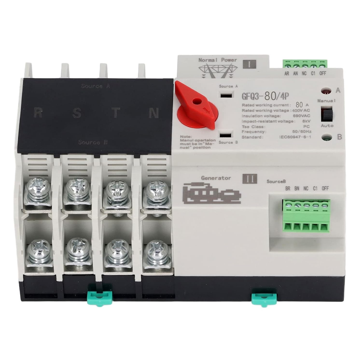
Figure 1: Front view of the GFQ3-80/4P ATS, showing terminals for Source A (Normal Power) and Source B (Generator), output terminals (R, S, T, N), and the Manual/Auto selector switch.

Figure 2: Angled view of the GFQ3-80/4P ATS, highlighting the red manual selector handle and control terminals.
4. Specifications
| Parameter | Value |
|---|---|
| Item Type | Dual Power Automatic Transfer Switch |
| Model | GFQ3-80/4P |
| Material | PC, Silver |
| Rated Current (Le) | 80A |
| Insulation Voltage (Ui) | AC690V |
| Rated Voltage (Ue) | AC400V |
| Frequency | 50/60Hz |
| Rated Control Voltage (Us) | 220VAC (85%Us-110%Us) |
| Grade | PC Grade |
| Poles | 4P |
5. Setup and Installation
The GFQ3-80/4P ATS is designed for easy installation on a standard 35mm DIN rail. Ensure all power is disconnected before proceeding with installation.
5.1 Mounting
- Locate a suitable 35mm DIN rail within your PZ30 distribution box or electrical panel.
- Align the ATS with the DIN rail. The device features a snap-on mechanism for secure attachment.
- Press the ATS firmly onto the DIN rail until it clicks into place. Ensure it is stable and does not wobble.

Figure 3: Illustration of the 35mm standard guide rail and snap installation method for the ATS.
5.2 Wiring
Refer to the wiring diagram on the device and the following instructions for proper connection. Ensure all connections are tight and secure.
- Source A (Normal Power): Connect the main power supply (e.g., utility grid) to the 'Source A' input terminals. These are typically labeled R, S, T, N for a 4-pole system.
- Source B (Backup Power): Connect the backup power supply (e.g., generator, UPS) to the 'Source B' input terminals. These are also typically labeled R, S, T, N.
- Load Output: Connect the electrical load (e.g., building's electrical system) to the output terminals of the ATS.
- Control Terminals: Connect the control wiring as per your system requirements. The device has terminals for 'Normal Power' and 'Generator' status monitoring and control.

Figure 4: Example of the ATS wired into an electrical panel, demonstrating connections to power sources and load.
6. Operating Instructions
The GFQ3-80/4P ATS offers both automatic and manual operation modes.
6.1 Automatic Mode
- Ensure the 'Manual/Auto' switch on the front panel is set to the 'Auto' position.
- In this mode, the switch will automatically monitor the main power supply (Source A).
- If Source A fails or its voltage drops below acceptable levels, the ATS will automatically switch the load to Source B (backup power) within milliseconds.
- When Source A is restored and stable, the ATS will automatically switch the load back to Source A.
6.2 Manual Mode
- Set the 'Manual/Auto' switch on the front panel to the 'Manual' position.
- To manually switch between Source A and Source B, use the red selector handle.
- Rotate the red handle to position 'I' to connect to Source A.
- Rotate the red handle to position 'II' to connect to Source B.
- Note: Manual operation overrides automatic functions. Always ensure the desired power source is available and stable before manual switching.
7. Maintenance
Regular maintenance ensures the longevity and reliable operation of your ATS.
- Visual Inspection: Periodically inspect the device for any signs of physical damage, loose connections, or overheating.
- Cleaning: Keep the device free from dust and debris. Use a dry, soft cloth for cleaning. Do not use liquid cleaners.
- Connection Checks: Ensure all terminal connections remain tight and secure. Loose connections can cause arcing and overheating.
- Functional Test: Periodically test the automatic transfer function by temporarily disconnecting the main power source to ensure the switch transfers to backup power correctly.
8. Troubleshooting
If you encounter issues with your ATS, refer to the following troubleshooting guide:
| Problem | Possible Cause | Solution |
|---|---|---|
| Device does not switch automatically | Switch is in Manual mode; No power from backup source; Faulty control circuit. | Set switch to 'Auto' mode; Check backup power supply; Consult a qualified electrician. |
| No power output | Both power sources are off; Loose wiring connections; Internal fault. | Verify both power sources are active; Check all wiring connections; Contact support. |
| Overheating | Loose connections; Overload; Insufficient ventilation. | Tighten all connections; Ensure load does not exceed rated current; Improve ventilation around the device. |
If the problem persists after attempting these solutions, please contact customer support.
9. Warranty and Support
For warranty information, technical support, or service inquiries, please refer to the documentation provided with your purchase or contact the seller directly. Keep your purchase receipt as proof of purchase.


