1. Introduction
This instruction manual provides detailed guidance for the installation, operation, and maintenance of the Pomya 16-Channel USB Opto-Isolated Relay Module. This module is designed to provide reliable ON/OFF switching control for various electrical equipment, making it suitable for applications in robotics, home automation, and other control systems. Please read this manual thoroughly before using the device to ensure proper functionality and safety.
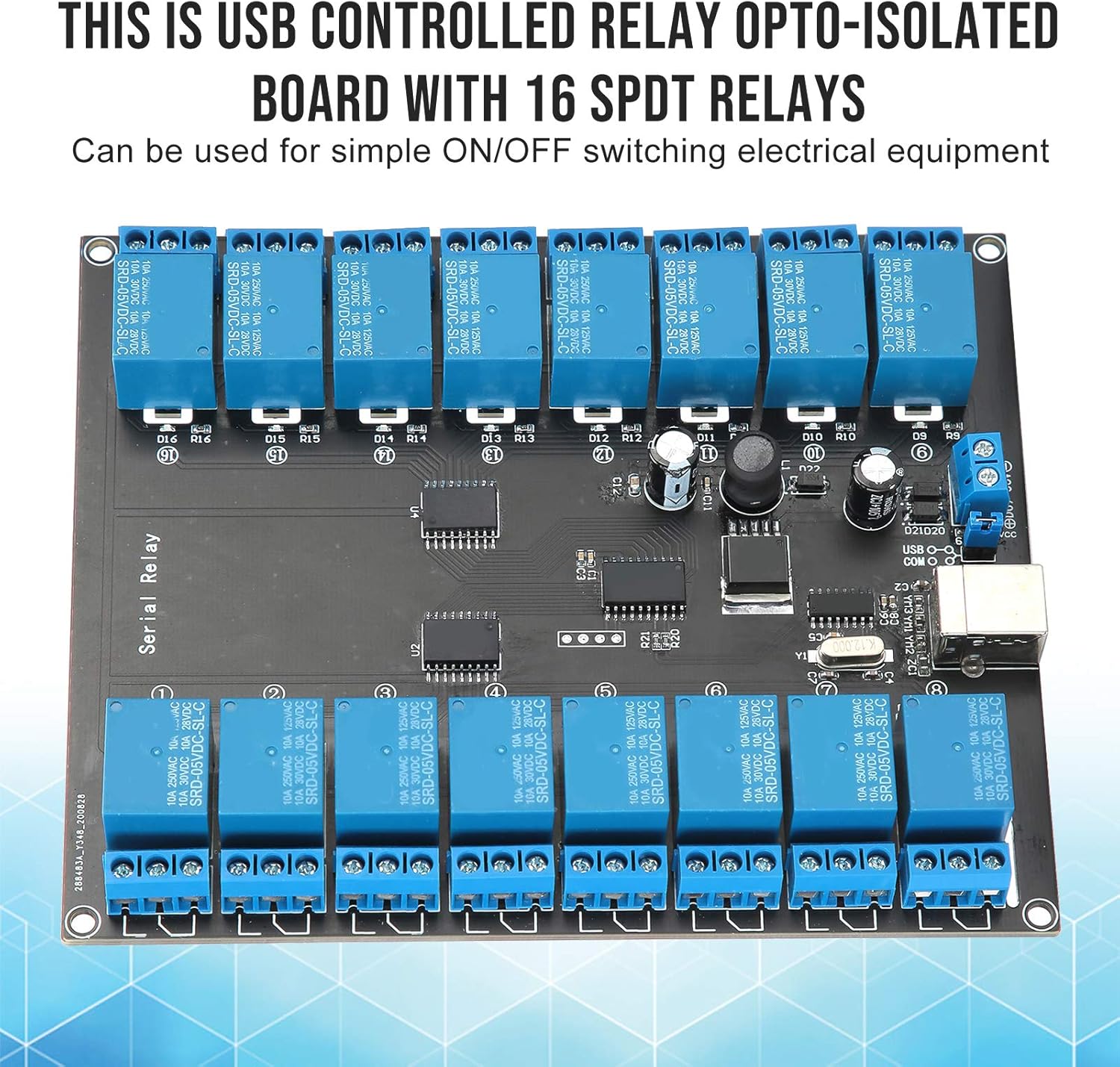
Image 1.1: Overview of the Pomya 16-Channel USB Opto-Isolated Relay Module, emphasizing its USB control and opto-isolation.
2. Product Features
The Pomya 16-Channel USB Opto-Isolated Relay Module offers the following key features:
- 16 SPDT Relays: Provides 16 independent Single-Pole Double-Throw (SPDT) relay switches for versatile control.
- USB Controlled: Easily connect and control the module via a standard USB interface from a computer.
- Opto-Isolated Design: Ensures electrical isolation between the control circuit (USB) and the relay switching circuits, enhancing safety and preventing interference.
- LED Power Indicator: A dedicated LED indicates the power status of the module.
- Individual Relay Status LEDs: Each relay has an associated LED to indicate its current ON/OFF state.
- High Load Capacity: Capable of switching loads up to 10 Amps at 250 Volts AC or 10 Amps at 30 Volts DC.
- Wide Power Supply Range: Operates with a DC input voltage between 7V and 38V.
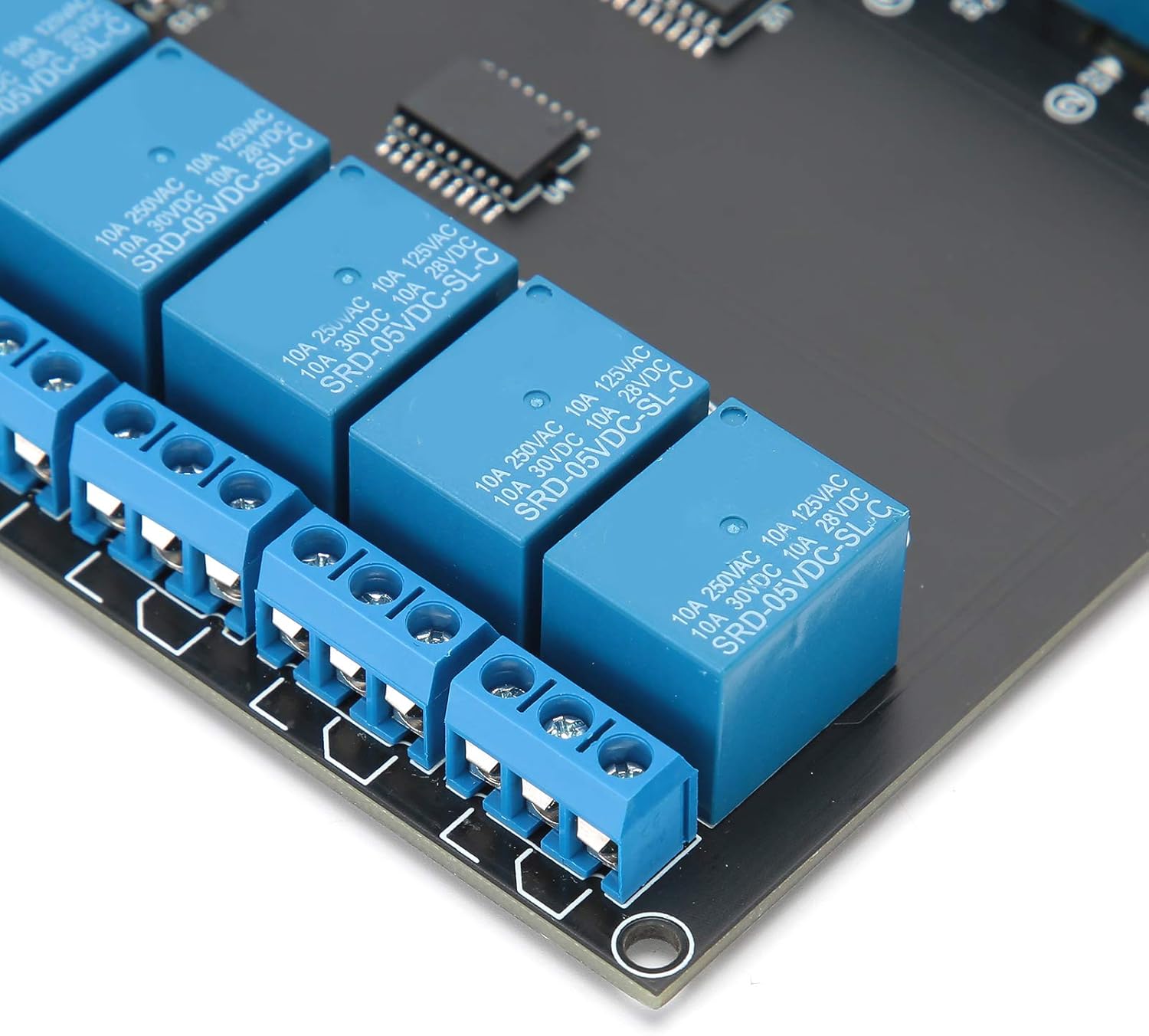
Image 2.1: Detailed view of the relay terminals and USB connection port.
3. Setup Instructions
Follow these steps to set up your Pomya 16-Channel USB Opto-Isolated Relay Module:
- Power Connection: Connect a DC power supply (7V-38V) to the designated power input terminals on the module. Ensure correct polarity. The power LED on the board should illuminate.
- USB Connection: Connect the module to your computer using a standard USB cable. The USB LED on the board should illuminate.
- Driver Installation: Your operating system may require specific drivers for the USB serial interface. A driver package, often including sample programs and hex codes for control, can typically be found at the manufacturer's support website or a provided download link. For example, a common resource for this type of board is this driver and software package.
- Identify COM Port: After driver installation, identify the assigned COM port for the relay module in your computer's Device Manager (Windows) or equivalent system utility.
- Serial Port Configuration: Configure your serial communication software (e.g., a terminal program or custom application) with the following settings:
- Baud Rate: 9600
- Device: D01600 (This may vary; refer to the specific software documentation or driver package for exact device identification.)
- Open Serial Port: Open the configured serial port in your software.
- Load Connections: Connect the electrical equipment you wish to control to the SPDT relay terminals. Each relay has three terminals: Common (COM), Normally Open (NO), and Normally Closed (NC). Refer to the wiring diagram for your specific application. Ensure the load does not exceed 10A/250V.
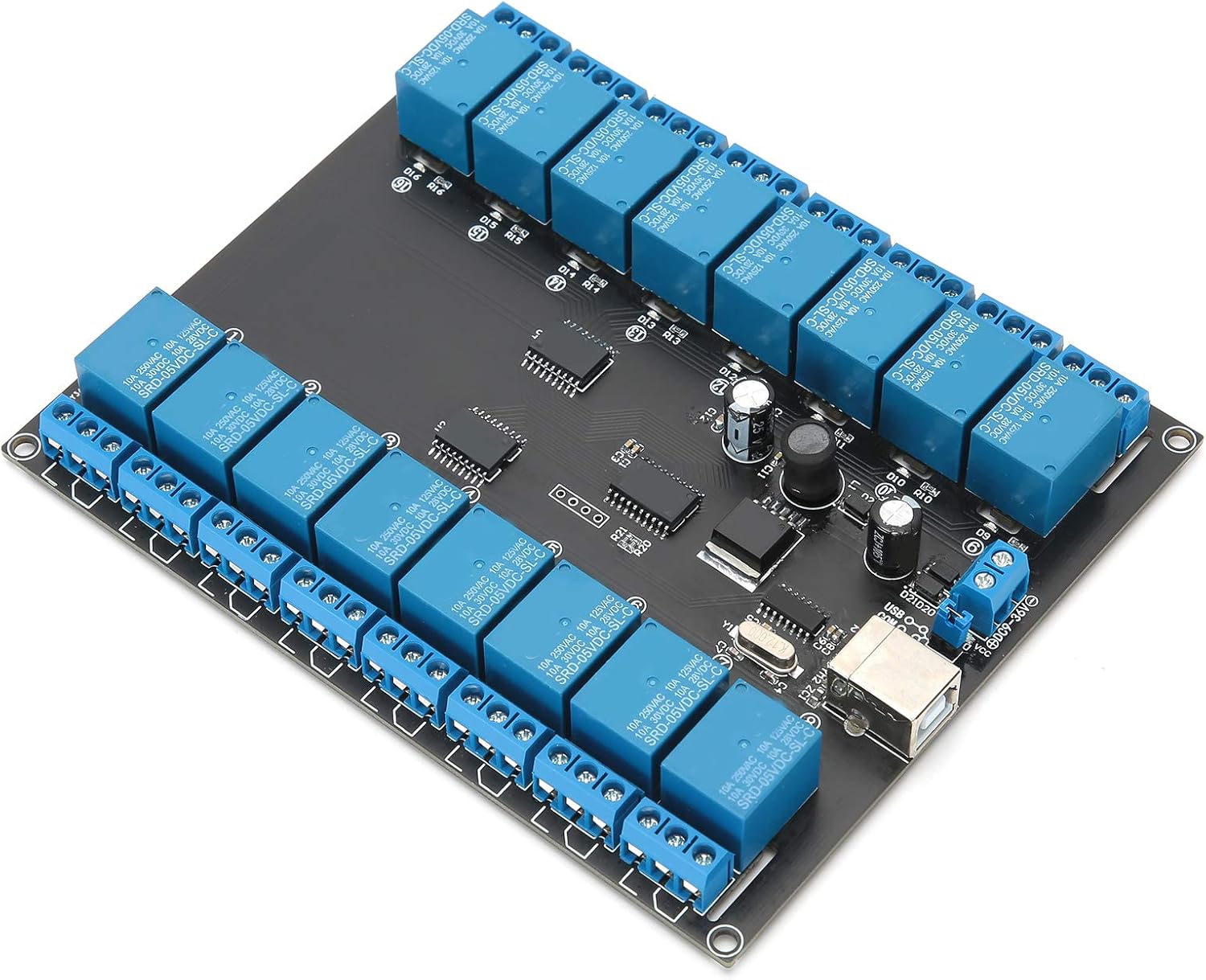
Image 3.1: Angled view of the module, highlighting the USB and power connections.
4. Operating Instructions
Once the module is set up and connected, you can control the relays by sending specific commands through the USB serial interface:
- Control Commands: Relays are typically controlled by sending specific hexadecimal (hex) codes to the configured COM port. These codes correspond to individual relays and their desired ON/OFF states. Refer to the documentation provided with the driver/software package for a complete list of hex codes for each relay.
- Relay Status Indication: Observe the individual LEDs next to each relay. A lit LED typically indicates that the corresponding relay is activated (e.g., the COM terminal is connected to the NO terminal).
- Sample Programs: The driver package often includes sample programs (e.g., in C++, Python, or other languages) that demonstrate how to send commands and control the relays programmatically. These can serve as a starting point for your own applications.
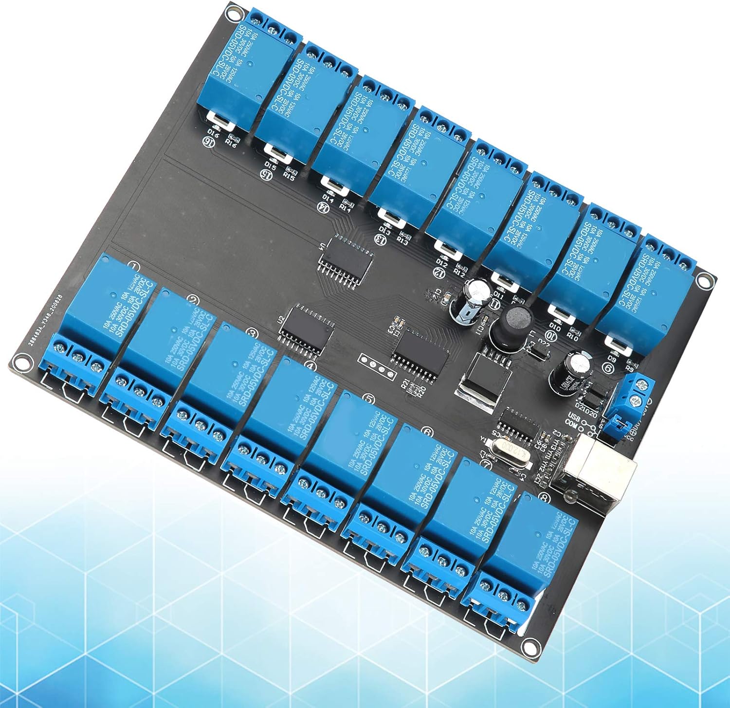
Image 4.1: Top-down view of the module, showing all 16 relays and their status indicators.
5. Maintenance
To ensure the longevity and reliable operation of your relay module, follow these maintenance guidelines:
- Keep Clean and Dry: Protect the module from dust, dirt, and moisture. Operate it in a clean, dry environment.
- Inspect Connections: Periodically check all power and load connections to ensure they are secure and free from corrosion.
- Avoid Overloading: Never exceed the maximum specified load of 10A/250V for any relay. Overloading can damage the relays and the module.
- Temperature Control: Operate the module within its specified temperature range to prevent overheating.
Image 5.1: Bottom view of the module, illustrating the circuit board layout.
6. Troubleshooting
If you encounter issues with your relay module, refer to the following troubleshooting steps:
- Module Not Powering On:
- Ensure the DC power supply (7V-38V) is correctly connected and providing power.
- Check the USB connection to the computer.
- Verify that the power LED on the board is illuminated.
- Relays Not Responding to Commands:
- Confirm that the USB drivers are correctly installed on your computer.
- Verify the assigned COM port in Device Manager.
- Check the serial communication settings in your software (Baud Rate: 9600, Device: D01600).
- Ensure you are sending the correct hex codes for the desired relay and state. Refer to the driver/software package documentation.
- Test with the sample program provided in the driver package, if available.
- Individual Relay LED Not Lighting Up:
- Check if the module is powered on and the power LED is lit.
- Verify that the command sent for that specific relay is correct.
- Inspect the relay for any visible damage.
- Connected Device Not Switching:
- Ensure the load is correctly wired to the relay's COM, NO, or NC terminals.
- Confirm that the load's voltage and current requirements do not exceed the relay's maximum rating (10A/250V).
- Test the relay's continuity with a multimeter if possible.
7. Specifications
| Feature | Specification |
|---|---|
| Brand | Pomya |
| Model Number | Pomyad5eoyqcg04 |
| Relay Type | 16 x SPDT (Single-Pole Double-Throw) |
| Control Interface | USB |
| Isolation | Opto-Isolated |
| Power Supply | DC 7V - 38V |
| Maximum Load | 10A / 250V AC, 10A / 30V DC |
| Material Type | Copper |
| Mounting Type | PCB Mount |
| Dimensions (L x W x H) | Approx. 19 x 18 x 4 cm (7.5 x 7.1 x 1.6 inches) |
| Weight | Approx. 287 g (0.63 lbs) |
8. Warranty and Support
For warranty information, technical support, or further assistance, please contact the seller or manufacturer directly. Retain your proof of purchase for any warranty claims.