JUNTEK PSG9080
JUNTEK PSG9080 Programmable Signal Generator User Manual
Model: PSG9080
1. Introduction
The JUNTEK PSG9080 is a high-performance programmable dual-channel function and arbitrary waveform generator. It is designed for a wide range of applications including scientific research, education, industrial control, and electronic product development. This manual provides detailed instructions on the setup, operation, maintenance, and troubleshooting of your PSG9080 device.
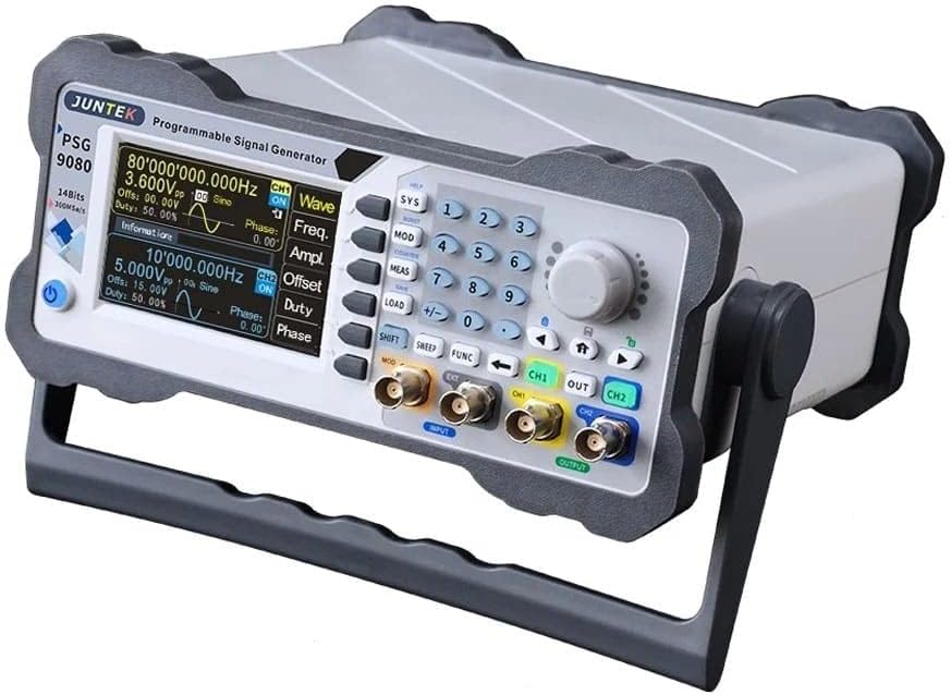
Figure 1.1: Front view of the JUNTEK PSG9080 Programmable Signal Generator, showing the display, control panel, and output ports.
2. Setup
2.1 Unboxing and Package Contents
Carefully unpack the signal generator and all accessories. Verify that all items listed below are present and undamaged. If any items are missing or damaged, please contact your vendor.

Figure 2.1: Packaging contents including the PSG9080 signal generator, power cable, USB data cable, BNC male plug test lead, and BNC to alligator clips test lead, along with the Quick Start guide.
- PSG9080 Signal Generator
- Power Cable
- BNC Male Plug Test Lead
- USB Data Cable
- BNC to Alligator Clips Test Lead
- Quick Start Guide
2.2 Connecting the Device
Before powering on the device, ensure all connections are secure.

Figure 2.2: Rear panel of the PSG9080, showing the AC power input, USB port, TTL Ext. port, and SYNC IN/OUT BNC connectors.
- Power Connection: Connect the provided power cable to the AC input port on the rear panel of the device. Plug the other end into a standard AC power outlet (AC 85-264V, 47-63Hz).
- Signal Output: Connect your test leads to the CH1 and CH2 output BNC connectors on the front panel.
- USB Connection (Optional): For PC control and firmware updates, connect the USB data cable from the device's USB port to your computer.
- External Synchronization (Optional): Use the SYNC IN/OUT BNC connectors for external triggering or synchronization with other equipment.
2.3 Initial Power-On
After connecting the power cable, press the power switch on the rear panel to turn on the device. The display will light up, and the system will perform a self-test before entering the main operating interface.

Figure 2.3: The System Setup screen, displaying model information, firmware versions, and options for clearing memory or updating firmware.
3. Operating Instructions
3.1 Control Panel Overview
The front panel features a clear LCD display, a numeric keypad, function buttons, and a rotary knob for parameter adjustment. Familiarize yourself with the layout for efficient operation.
3.2 Waveform Generation
The PSG9080 supports various standard and arbitrary waveforms.
- Selecting Waveform Type: Use the 'Wave' button or corresponding menu options to select between Sine, Square, Triangle, Pulse, TTL, or Arbitrary waveforms.
- Frequency Adjustment: The frequency range for sine waves is 1 nHz-80 MHz. For square waves, it's 1 nHz-30 MHz. Triangle waves range from 1 nHz-50 MHz. Pulse waves and TTL digital waves are 1 nHz-30 MHz and 1 nHz-20 MHz respectively. Arbitrary waves have a range of 1 nHz-50 MHz. Use the numeric keypad and rotary knob to set the desired frequency.
- Amplitude and Offset: Adjust the output signal's amplitude (Vpp) and DC offset using the dedicated controls. The output signal can range from 1 MHz to 25 Vpp.
- Duty Cycle: For square and pulse waves, the duty cycle can be adjusted to modify the waveform's characteristics.

Figure 3.1: Display showing an arbitrary waveform selection and its graphical representation.
3.3 Dual-Channel Output
The PSG9080 features two independent output channels (CH1 and CH2) with equivalent performance.
- Independent Control: Each channel's parameters (waveform type, frequency, amplitude, offset, duty cycle) can be set independently.
- Phase Adjustment: The phase difference between CH1 and CH2 is continuously adjustable from 0 to 359.9 degrees, allowing for precise phase-related testing.
3.4 Advanced Functions
- Programmable Output: The device allows you to formulate the waveform output type, output time, and output sequence freely to achieve automated testing and complex signal generation.
- Modulation Function: Modulated waveforms can be output on single or dual channels. This function allows for adding information from a signal source to a carrier wave, making it suitable for channel transmission and various communication tests.
- Voltage-Controlled Adjustment (VCA): The frequency, amplitude, and duty cycle of the output can be controlled by an external analog voltage signal. This feature is widely used in industrial debugging for voltage-controlled sweep frequency, sweep amplitude, and sweep duty cycle applications.
- Measurement Mode: The device can also function in measurement mode to display frequency, positive/negative pulse width, period, and duty cycle.

Figure 3.2: Various display options within the Measurement Mode, showing frequency, pulse width, period, and duty cycle measurements.
3.5 Firmware Update
The firmware can be updated in real-time to correct bugs or for special customization needs. Connect the device to a PC via USB and follow the instructions in the PC software to perform a one-key firmware update.
4. Maintenance
- Cleaning: Use a soft, dry cloth to clean the exterior of the device. Do not use abrasive cleaners or solvents. Ensure the device is powered off and unplugged before cleaning.
- Storage: When not in use for extended periods, store the device in a cool, dry place away from direct sunlight and extreme temperatures.
- Ventilation: Ensure the ventilation openings on the device are not obstructed to prevent overheating.
5. Troubleshooting
This section addresses common issues you might encounter with the PSG9080.
| Problem | Possible Cause | Solution |
|---|---|---|
| Device does not power on. | Power cable not connected or faulty; power switch off; no power from outlet. | Check power cable connection; ensure power switch is ON; test power outlet. |
| No signal output. | Output channel disabled; amplitude set to zero; incorrect waveform parameters. | Ensure output channel is enabled; increase amplitude; verify frequency and other parameters. |
| Display is blank or frozen. | System error; temporary software glitch. | Restart the device. If the problem persists, consider a firmware update. |
| Inaccurate frequency/amplitude. | Calibration needed; external interference. | Refer to the advanced settings for calibration options or contact support. Ensure a stable environment. |
6. Specifications
Detailed technical specifications for the JUNTEK PSG9080.

Figure 6.1: Dimensions of the PSG9080, approximately 247mm (width) x 243mm (depth) x 102mm (height).
| Parameter | Value |
|---|---|
| Manufacturer | RF Elettronica |
| Model | PSG9080 |
| Sine Wave Frequency Range | 1 nHz - 80 MHz |
| Square Wave Frequency Range | 1 nHz - 30 MHz |
| Triangle Wave Frequency Range | 1 nHz - 50 MHz |
| Pulse Wave Frequency Range | 1 nHz - 30 MHz |
| TTL Digital Wave Frequency Range | 1 nHz - 20 MHz |
| Arbitrary Wave Frequency Range | 1 nHz - 50 MHz |
| Minimum Resolution Frequency | 1 nHz |
| Frequency Accuracy | ± 5ppm (0 to 50 °C) |
| Frequency Stability | ± 3ppm (for 1 year) |
| Pulse Width Adjustment Range | 5nS - 4S |
| Pulse Period Adjustment Range | 10nS - 40S |
| Output Signal Voltage | 1 MHz - 25 Vpp |
| Power Supply | AC 85-264V, 47-63Hz |
| Max Power Consumption | 30W |
| Fuse | 250Vac, T3.15A |
| ASIN | B0C2CL3S1P |
7. Warranty and Support
For warranty information and technical support, please refer to the documentation provided with your purchase or contact the seller/manufacturer directly. Information regarding spare parts availability is currently unavailable.