HYDRAULIC PRO E5106
HYDRAULIC PRO 10,000 PSI Air Hydraulic Pump Instruction Manual
Model: E5106
1. Introduction
This manual provides essential information for the safe and efficient operation, maintenance, and troubleshooting of your HYDRAULIC PRO 10,000 PSI Air Hydraulic Pump. This robust pump is designed for various industrial and construction applications, including powering rams, presses, and hydraulic pullers, particularly in auto body frame machines and hydraulic press systems. Please read this manual thoroughly before operating the pump to ensure proper usage and to prevent injury or damage.

Figure 1: HYDRAULIC PRO 10,000 PSI Air Hydraulic Pump (Model E5106) with remote control.
2. Safety Information
Always adhere to the following safety guidelines to ensure personal safety and prevent damage to the equipment.
- Read the Manual: Fully understand all instructions and warnings before operating the pump.
- Personal Protective Equipment (PPE): Always wear appropriate safety glasses, gloves, and protective footwear when operating or maintaining the pump.
- Work Area: Ensure the work area is clean, well-lit, and free from obstructions. Keep bystanders away from the operating equipment.
- Air Supply: Connect the pump only to a clean, dry air supply within the specified pressure range (110-145 PSI). Do not exceed the maximum input air pressure.
- Hydraulic Fluid: Handle hydraulic fluid with care. Refer to the Material Safety Data Sheet (MSDS) for specific handling and disposal instructions. Ensure the reservoir is adequately filled before operation.
- Connections: Ensure all hydraulic and air connections are secure and free from leaks before applying pressure. Use appropriate NPT fittings.
- Overpressure Protection: The pump is equipped with a safety relief valve. Do not tamper with or bypass this valve.
- Remote Control: Utilize the remote control for safe operation, maintaining a safe distance from the hydraulic application.
- Maintenance: Disconnect the air supply and relieve all hydraulic pressure before performing any maintenance or adjustments.
- Storage: Store the pump in a clean, dry environment, protected from extreme temperatures and corrosive substances.
3. Product Overview
3.1 Key Features
- High Pressure Output: Maximum adjustable pressure of 10,000 PSI, suitable for 10-ton applications.
- Large Reservoir: 2.3L (0.6 gal) aluminum alloy oil reservoir, pre-filled with hydraulic fluid.
- Remote Control: 9.8 ft (118 inch) extended wiring for convenient and safe operation of up and down functions.
- Durable Construction: Features a high-quality aviation aluminum pump core and a robust metal shell designed for tough industrial environments.
- Safety Relief Valve: Built-in internal relief valve protects hydraulic components from overpressure and prevents oil leaks.
- Standard Connections: 3/8" NPT quick hydraulic coupler for oil outlet and 1/4" NPT inlet for air.
3.2 Components
The HYDRAULIC PRO Air Hydraulic Pump consists of the following main components:
- Pump Unit: The main body containing the hydraulic pump mechanism, motor, and oil reservoir.
- Oil Reservoir: 2.3L capacity tank for hydraulic fluid.
- Remote Control: Handheld unit with "UP" and "DOWN" buttons for controlling hydraulic movement, connected via a 9.8 ft cable.
- Oil Outlet (NPT 3/8"): Connection point for the hydraulic hose to the cylinder or tool.
- Air Inlet (NPT 1/4"): Connection point for the compressed air supply.
- Pressure Adjustment Valve: Allows for setting the maximum output pressure.
- Portable Handle: Integrated handle for easy transport.
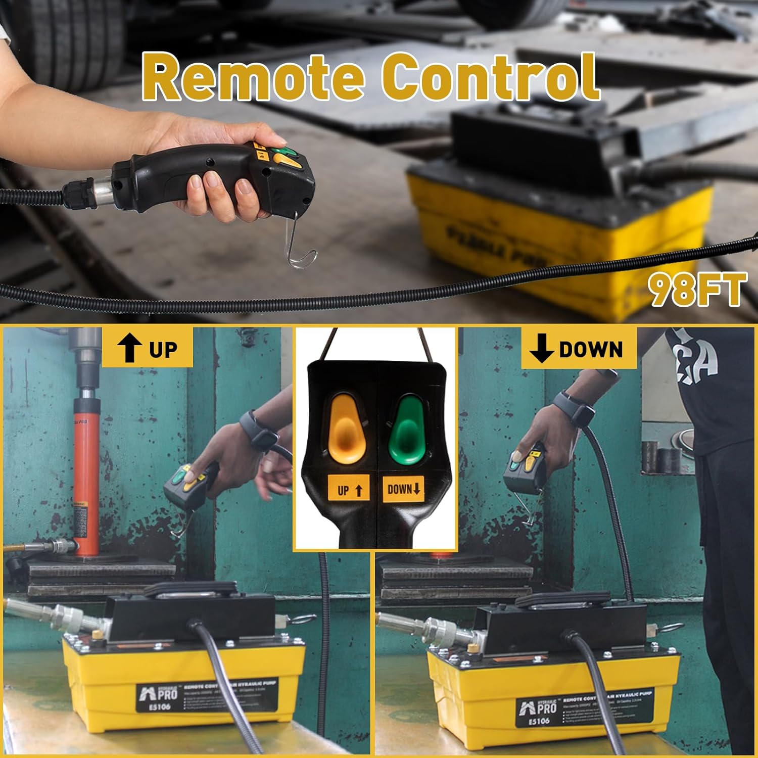
Figure 2: Remote Control for precise and safe operation.

Figure 3: Quick Hydraulic Coupler (Oil Outlet NPT 3/8") and Air Inlet (NPT 1/4").
4. Setup
Follow these steps to set up your air hydraulic pump:
- Unpacking: Carefully remove the pump from its packaging. Inspect for any signs of damage during transit.
- Placement: Place the pump on a stable, level surface near your hydraulic application.
- Hydraulic Connection:
- Apply PTFE tape to the threads of the quick connector for the oil outlet.
- Screw the quick connector securely into the NPT 3/8" oil outlet on the pump.
- Connect your hydraulic hose from the quick connector to your single-acting cylinder or hydraulic tool. Ensure a tight, leak-free connection.
- Air Connection:
- Screw the air intake fitting into the NPT 1/4" air inlet on the pump.
- Connect your compressed air line to the air intake fitting. Ensure your air compressor can supply 110-145 PSI.
- Check Hydraulic Fluid Level: The pump comes pre-filled. Verify the hydraulic fluid level in the 2.3L reservoir. If needed, add AW-46 hydraulic oil.
- Exhaust Valve: Before initial use, open the exhaust valve for approximately 5 seconds to release any trapped air, then close it.

Figure 4: Quick Connection Operation Steps.
5. Operating Instructions
Once the pump is properly set up and connected, follow these steps for operation:
- Connect Air Supply: Ensure the air supply is connected and providing the required pressure (110-145 PSI).
- Activate Pump: To extend the hydraulic cylinder or apply pressure, press and hold the Yellow (UP) button on the remote control. The pump will activate and build hydraulic pressure.
- Maintain Pressure: Release the Yellow (UP) button to hold the pressure at the current level.
- Release Pressure: To retract the hydraulic cylinder or release pressure, press and hold the Green (DOWN) button on the remote control.
- Monitor Operation: Always monitor the hydraulic performance and the application during operation.
- Shut Down: When finished, release all hydraulic pressure, disconnect the air supply, and store the pump properly.
This pump is ideal for various applications including:
- Automobile Repair
- Frame Straighteners
- Hydraulic Elevating Platforms
- Hydraulic Presses

Figure 5: Wide Application of the Air Hydraulic Pump.
6. Maintenance
Regular maintenance ensures the longevity and optimal performance of your HYDRAULIC PRO Air Hydraulic Pump.
- Hydraulic Fluid Check: Periodically check the hydraulic fluid level. Ensure it is within the recommended range. Use only AW-46 hydraulic oil for refills.
- Fluid Replacement: Replace hydraulic fluid according to the manufacturer's recommendations or if it appears contaminated.
- Cleanliness: Keep the pump clean and free from dirt, dust, and debris. Wipe down the exterior regularly.
- Connections: Regularly inspect all air and hydraulic connections for leaks or damage. Tighten or replace fittings as necessary.
- Air Filter: If your air supply has an inline filter, ensure it is clean and functioning correctly to prevent contaminants from entering the pump.
- Storage: Store the pump in a dry, protected area when not in use. Ensure all pressure is relieved before storage.

Figure 6: 2.3L Oil Tank and Oil Leakage Prevention Device.
7. Troubleshooting
Refer to the table below for common issues and their potential solutions.
| Problem | Possible Cause | Solution |
|---|---|---|
| Pump does not build pressure. | Low air pressure; Air leak in system; Low hydraulic fluid; Clogged air inlet. | Ensure air supply is 110-145 PSI; Check all air and hydraulic connections for leaks; Top up hydraulic fluid; Clean air inlet filter. |
| Hydraulic cylinder retracts slowly or not at all. | Exhaust valve not fully open; Obstruction in hydraulic line; Low hydraulic fluid. | Ensure the Green (DOWN) button is fully pressed; Check hydraulic lines for kinks or blockages; Check and top up hydraulic fluid. |
| Oil leakage. | Loose fittings; Damaged seals; Overfilled reservoir. | Tighten all connections; Inspect and replace damaged seals; Ensure fluid level is correct. |
| Pump runs continuously without building pressure. | Internal pump issue; Significant air leak. | Contact customer support; Thoroughly check all air connections. |
8. Technical Specifications
| Parameter | Value |
|---|---|
| Maximum Adjustable Pressure | 10,000 PSI |
| Output Oil Volume | 98 cubic inches / 1.6 liters |
| Oil Tank Capacity | 2.3 L / 0.6 gal |
| Hydraulic Oil Type | AW-46 |
| Oil Outlet Connector | NPT 3/8" quick hydraulic coupler |
| Air Inlet Connector | NPT 1/4" |
| Max Input Air Pressure | 110 psi - 145 psi |
| Remote Control Cable Length | 9.8 ft (118 inches) |
| Net Weight | 19.16 pounds (8.2 kg) |
| Product Dimensions (L x W x H) | 12.4 x 6.77 x 7.87 inches |
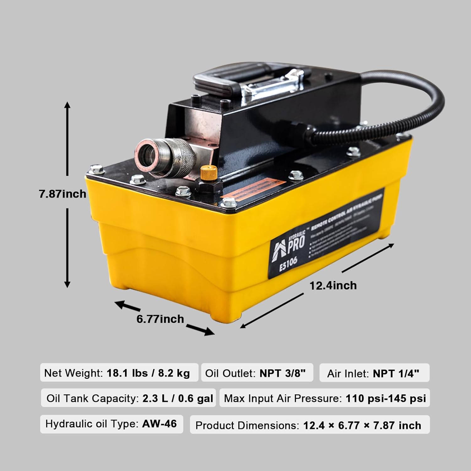
Figure 7: Product Dimensions and Key Specifications.
9. Warranty and Support
HYDRAULIC PRO products are manufactured to high-quality standards. For information regarding warranty coverage, technical support, or replacement parts, please refer to the warranty card included with your product or visit the official HYDRAULIC PRO website. You may also contact customer service through the retailer where the product was purchased.
For direct inquiries, please have your product model number (E5106) and purchase date available.
Ask a question about this manual
Ask about setup, troubleshooting, compatibility, parts, safety, or missing instructions. Manuals+ will review the question and use this page’s manual context to help answer it.