1. Introduction
The Fafeicy GX591 Spot Welder Control Board is a versatile and portable solution designed for spot welding applications, particularly for lithium battery packs such as 26650 and 32650 cells. This control board offers stable and reliable performance, featuring a digital display for real-time information and adjustable power settings to suit various welding needs. Its compact design makes it suitable for both professional and DIY use.

Image 1.1: Overview of the GX591 Spot Welder Control Board.
2. Safety Information
Please read and understand all safety instructions before operating the GX591 Spot Welder Control Board. Failure to follow these instructions may result in electric shock, fire, or serious injury.
- Electrical Hazard: This device operates with high current. Always ensure proper insulation and avoid direct contact with live circuits.
- Power Source: Use only recommended power sources with appropriate voltage and current capabilities. Incorrect power sources can damage the device or cause hazards.
- Battery Handling: Exercise caution when working with lithium batteries. Ensure batteries are not short-circuited, overcharged, or physically damaged.
- Ventilation: Operate in a well-ventilated area to dissipate any fumes or heat generated during welding.
- Personal Protective Equipment (PPE): Always wear appropriate PPE, including safety glasses, gloves, and non-conductive footwear.
- Children and Pets: Keep the device out of reach of children and pets.
- Storage: Store the control board in a dry, cool place away from flammable materials.
3. Package Contents
Verify that all items listed below are included in your package:
- 1 x Spot Welder Control Board (GX591)
- 2 x Connecting Cable
- 4 x Nut
- 4 x Screw
- 1 x Bar (likely nickel strip for welding)
- 2 x Spot Welding Pen

Image 3.1: Contents included with the GX591 Spot Welder Control Board.
4. Specifications
| Feature | Specification |
|---|---|
| Item Type | Spot Welder Control Board |
| Material | PCB Red Copper |
| Product Model | GX591 |
| Product Use | 26650 32650 Lipo battery welding, portable, stable and reliable |
| System Voltage | 8-24V DC |
| Welding Peak Current | 2400A maximum |
| Standby Power Consumption | Less than 0.5mA |
| Weld Thickness | 0.1-0.2mm |
| Package Dimensions | 5.91 x 3.94 x 1.18 inches (150 x 100 x 30 mm) |
| Item Weight | 5.43 ounces (154 grams) |
4.1. Power Supply Requirements
The performance of the spot welder is highly dependent on the quality of the power source. Ensure your power source meets the following criteria:
- Acid Battery: Battery car battery: 20AH x 2 (new)
- New Car Starter Battery: 36-45AH
- Model Battery: 3S4000MAH 35C, 3S 5000MAH 25C, 3S 8000MAH 20C
- Car Starter Power: 11.5-14.8V, 36-60AH. Internal resistance should be greater than 2.5 milliohms, but less than 7 milliohms.
- Self-Assembled Battery: 11.5-14.8V. Requires a total internal resistance of less than 7 milliohms.
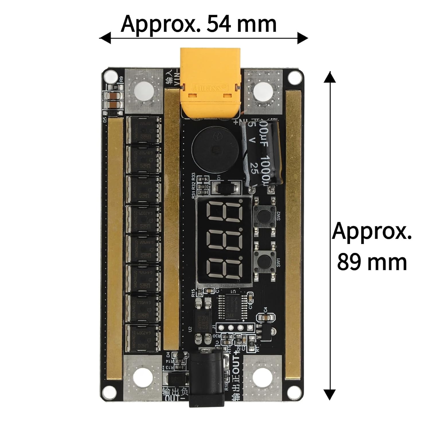
Image 4.1: Approximate dimensions of the GX591 Spot Welder Control Board.
5. Setup and Wiring
The GX591 Spot Welder Control Board is designed for direct installation and use. Follow the wiring diagram carefully to ensure correct connections.
5.1. Component Identification

Image 5.1: Labeled components of the GX591 Spot Welder Control Board.
- Power Input (+/-): Connect your DC power source here. The board features a TX60 connector for positive input and a screw terminal for negative input.
- Solder Pen Output (+/-): Connect the spot welding pens to these terminals. Ensure correct polarity (red for positive, black for negative).
- Foot Switch Interface: An optional port for connecting an external foot switch to trigger welding pulses.
- Digital Display: Shows real-time gear settings and voltage.
- Control Buttons (SW1, SW2): Used for adjusting settings and power levels.
- Buzzer: Provides audible feedback for operations and alarms.
- MOS Tubes: Eight integrated MOS tubes handle the high welding current.
5.2. Wiring Diagram

Image 5.2: Wiring diagram for connecting the GX591 Spot Welder Control Board to a battery and welding pens.
Connect the positive terminal of your power source to the Positive Input (TX60 connector) on the board. Connect the negative terminal of your power source to the Negative Input screw terminal. Then, connect the red welding pen to the Solder Pen Output + and the black welding pen to the Solder Pen Output -. Ensure all connections are secure and observe polarity.
6. Operation
The GX591 Spot Welder Control Board features a digital display and control buttons for easy operation.
6.1. Power On/Off
- To turn on: Long press the
Ask a question about this manual
Ask about setup, troubleshooting, compatibility, parts, safety, or missing instructions. Manuals+ will review the question and use this page’s manual context to help answer it.