ADI 1025
Applikon ADI 1025 Bio Console Instruction Manual
Model: ADI 1025 | Brand: Generic
1. Introduction
This instruction manual provides essential information for the safe and efficient operation, setup, and maintenance of the Applikon ADI 1025 Bio Console. This device is designed for precise control and monitoring in various biological applications. Please read this manual thoroughly before operating the unit to ensure proper function and to prevent damage or injury.
2. Safety Information
Adherence to safety guidelines is paramount for the protection of personnel and equipment. Always observe the following precautions:
- Electrical Safety: Ensure the unit is connected to a properly grounded power outlet with the correct voltage as specified on the device label. Do not operate with damaged power cords.
- Ventilation: Position the console in an area with adequate ventilation to prevent overheating. Do not block ventilation openings.
- Liquid Spills: Avoid liquid spills on or into the console. In case of a spill, immediately disconnect power and allow the unit to dry completely before re-connecting.
- Gas Connections: Ensure all gas connections (Air, CO2) are secure and leak-free. Use appropriate pressure regulators for gas supply.
- Biological Hazards: When working with biological samples, follow all standard laboratory safety procedures, including proper handling of biohazardous materials and waste disposal.
- Qualified Personnel: Operation and maintenance should only be performed by trained and qualified personnel.
3. Product Overview and Components
The Applikon ADI 1025 Bio Console integrates various control and monitoring functions for bioreactor systems. Key components are detailed below:

Figure 3.1: Front view of the Applikon ADI 1025 Bio Console, showing the main control panel, gas flow meters, and pump connection points.
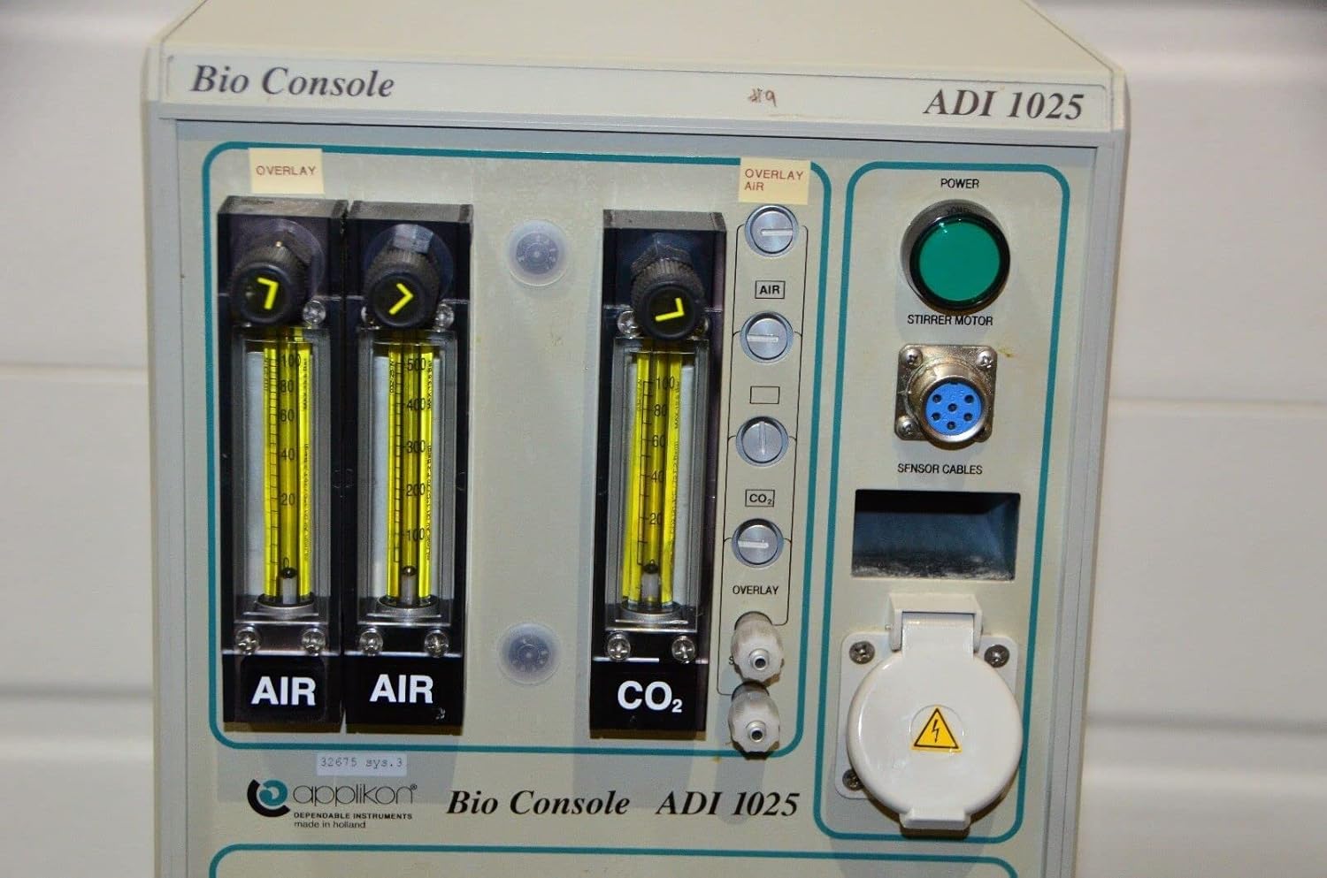
Figure 3.2: Detailed view of the front panel, highlighting the Air and CO2 flow meters, Overlay Air controls, Power button, Stirrer Motor connector, and Sensor Cables input.
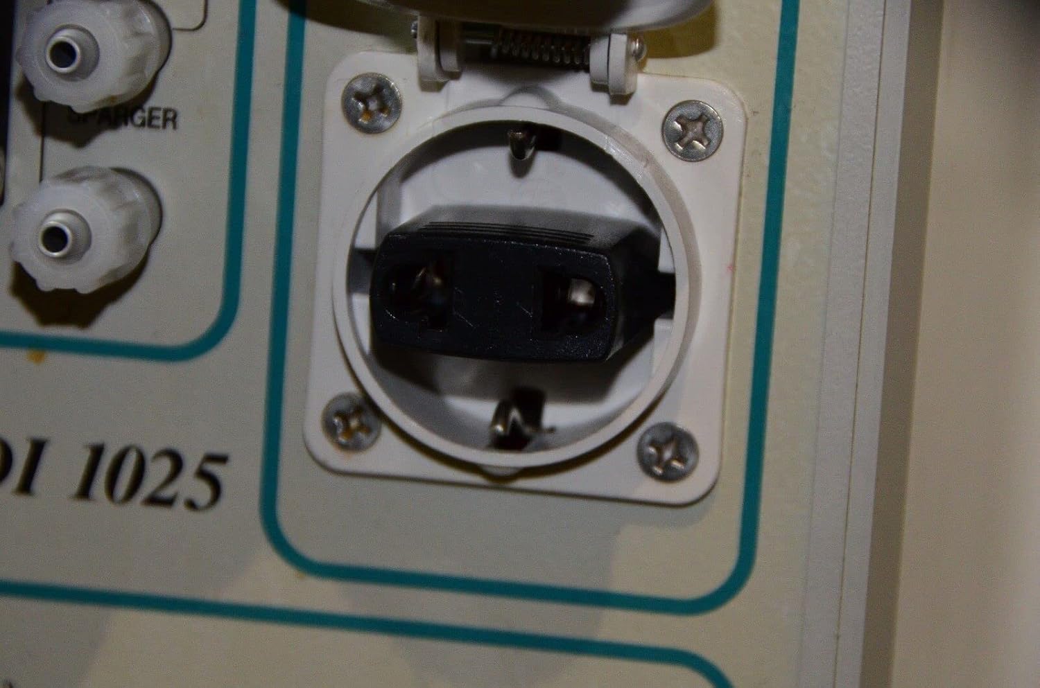
Figure 3.3: Close-up of the auxiliary power outlet located on the front panel, typically used for external devices.

Figure 3.4: Lower front panel connections, including ports labeled "CONDENSER FROM" and "REACTOR FROM/TO", indicating fluid or gas pathways.

Figure 3.5: Rear view of the console, displaying the main power input, outputs to bio controller and power unit, gas inlets (CO2, Air, Overlay Air), I/O signals port, and water inlet/outlet for flow condenser.

Figure 3.6: Detailed view of one of the rear product labels, showing "Applikon Dependable Instruments", model ADI Z510100110, year 2003, voltage 220-240 / 110-120 Vac 50/60 Hz, power 1600 VA, and fuse rating T 5A/T 10A.

Figure 3.7: Detailed view of a second rear product label, showing model ADI Z310250010, year 2003, voltage 220-240 / 110-120 Vac 50/60 Hz, power 1600 VA, and fuse rating T 8A / T 16A. Note the variation in model number and fuse rating compared to Figure 3.6, indicating potential product variations.

Figure 3.8: Close-up of the main green Power button and the multi-pin connector for the Stirrer Motor on the front panel.
Key Components:
- Front Panel: Features gas flow meters (Air, CO2), overlay air controls, main power button, stirrer motor connector, sensor cable input, and auxiliary power outlet.
- Pump Connections: Designated areas for connecting external pumps (PUMP 1, PUMP 2, PUMP 3).
- Rear Panel: Includes main power input, outputs for bio controller and power unit, gas inlets, I/O signals port, and connections for flow condenser water.
- Internal Components: (Not visible externally) Control circuitry for precise regulation of parameters.
4. Setup
Proper setup is crucial for the optimal performance and longevity of the ADI 1025 Bio Console.
- Unpacking and Inspection:
Carefully remove the console from its packaging. Inspect the unit for any signs of shipping damage. Report any damage to the carrier and supplier immediately.
- Placement:
Place the console on a stable, level surface in a laboratory environment. Ensure there is sufficient clearance around the unit for proper ventilation, especially at the rear panel where air vents are located. Avoid direct sunlight, excessive heat, or high humidity.
- Power Connection:
Before connecting to power, verify that the voltage selector (if present, or check the rear label as shown in Figure 3.6 and 3.7) matches your local power supply (220-240 Vac or 110-120 Vac, 50/60 Hz). Connect the main power cord to the appropriate inlet on the rear panel (see Figure 3.5) and then to a grounded electrical outlet.
- Gas Connections:
Connect regulated gas lines for Air and CO2 to the corresponding inlets on the rear panel (see Figure 3.5). Ensure all connections are tight and leak-free. The front panel features flow meters for precise control of these gases (see Figure 3.2).
- External Device Connections:
- Stirrer Motor: Connect the stirrer motor cable to the designated multi-pin connector on the front panel (see Figure 3.8).
- Sensor Cables: Connect relevant sensor cables (e.g., pH, DO, temperature) to the "SENSOR CABLES" input on the front panel.
- Pumps: Connect external pumps to the designated pump control ports (PUMP 1, PUMP 2, PUMP 3) on the front panel.
- Condenser/Reactor: Connect tubing for the condenser and reactor to the ports on the lower front panel (see Figure 3.4) and the water inlet/outlet for the flow condenser on the rear panel (see Figure 3.5).
- I/O Signals: If integrating with external control systems, connect the I/O signals cable to the D-sub connector on the rear panel (see Figure 3.5).
5. Operating Instructions
This section outlines the basic steps for operating the Applikon ADI 1025 Bio Console.
- Powering On:
Once all connections are secure, press the green "POWER" button on the front panel (see Figure 3.8) to turn on the console. The indicator light will illuminate.
- Gas Flow Control:
Adjust the flow rates for Air and CO2 using the respective knobs above the flow meters on the front panel (see Figure 3.2). Monitor the flow rates directly on the rotameters. The "OVERLAY AIR" control allows for separate air flow to the headspace of the bioreactor.
- Stirrer Motor Operation:
Ensure the stirrer motor is properly connected. The console provides control for the stirrer motor, typically through an external bio controller connected via the "TO BIO CONTROLLER" port on the rear (see Figure 3.5).
- Sensor Monitoring:
If sensors are connected, their signals will be processed by the console and typically relayed to an external bio controller for display and data logging.
- Pump Control:
The console provides interfaces for controlling external pumps (PUMP 1, PUMP 2, PUMP 3). Refer to the specific pump manuals for their operation, as the console acts as a control interface.
- Powering Off:
To turn off the console, press the green "POWER" button again. Disconnect the main power cord from the wall outlet if the unit will not be used for an extended period.
6. Maintenance
Regular maintenance ensures the longevity and reliable performance of your Applikon ADI 1025 Bio Console.
- Cleaning:
Wipe the exterior of the console with a soft, damp cloth. For stubborn stains, a mild detergent can be used. Do not use abrasive cleaners or solvents. Ensure no liquids enter the ventilation openings or connectors.
- Connection Checks:
Periodically inspect all electrical, gas, and fluid connections for wear, damage, or leaks. Replace any worn or damaged tubing and cables immediately.
- Ventilation:
Ensure that the ventilation grilles on the rear panel remain clear of dust and debris to prevent overheating. Use a soft brush or compressed air to clean them if necessary.
- Calibration:
While the console itself primarily acts as a control unit, ensure that any connected sensors (pH, DO, etc.) and pumps are calibrated according to their respective manufacturer's instructions to maintain accuracy.
- Storage:
If storing the unit for an extended period, disconnect all cables, clean the unit, and store it in a dry, dust-free environment within the specified operating temperature range.
7. Troubleshooting
This section provides solutions to common issues you might encounter with the Applikon ADI 1025 Bio Console. For problems not listed here, contact technical support.
| Problem | Possible Cause | Solution |
|---|---|---|
| Unit does not power on. |
|
|
| Gas flow meters show no flow. |
|
|
| Stirrer motor not operating. |
|
|
8. Specifications
The following specifications apply to the Applikon ADI 1025 Bio Console:
| Parameter | Value |
|---|---|
| Model Number | ADI 1025 |
| Manufacturer Part Number (MPN) | 1025 |
| Brand | Generic (Applikon Dependable Instruments) |
| ASIN | B0BZXLP362 |
| Color | Black (console housing is light grey/beige) |
| Date First Available | February 15, 2019 |
| Input Voltage | 220-240 Vac / 110-120 Vac (selectable/configurable) |
| Frequency | 50/60 Hz |
| Power Consumption | 1600 VA |
| Fuse Rating (Example 1) | T 5A / T 10A (refer to specific unit label) |
| Fuse Rating (Example 2) | T 8A / T 16A (refer to specific unit label) |
| Year of Manufacture (Example) | 2003 (refer to specific unit label) |
Note: Specific electrical ratings and model variations may differ. Always refer to the product label on your specific unit for precise specifications.
9. Warranty and Support
Information regarding the warranty period and specific support contacts for the Applikon ADI 1025 Bio Console is not available in this document. For warranty claims, technical support, or service inquiries, please contact the original vendor or manufacturer directly. Ensure you have your product's serial number and purchase details ready when contacting support.
No official product videos from the seller were provided in the available data for inclusion in this manual.
Ask a question about this manual
Ask about setup, troubleshooting, compatibility, parts, safety, or missing instructions. Manuals+ will review the question and use this page’s manual context to help answer it.