1. Introduction
This manual provides essential information for the installation, operation, and maintenance of your Silscvtt Brushless Motor Speed Controller. This controller is designed for electric bicycles and scooters, offering stable speed control and responsive braking.
2. Product Specifications
| Specification | Value |
|---|---|
| Battery Voltage | 36-48V 350W |
| Brake Type | High/Low Electrical Level |
| Phase Angle Identification | 60° /120° Automatic Identification |
| Length | 4.09 inches (10.39 cm) |
| Width | 2.83 inches (7.19 cm) |
| Height | 1.65 inches (4.19 cm) |
| Item Weight | 6.7 ounces (190 grams) |
| Compatibility | Electric bicycles, scooters |
3. Product Features
- The controller shell is constructed from durable aluminium alloy with a groove design for efficient heat dissipation.
- Provides steady speed control and sensitive response for braking and direction changes.
- Features a 2-mode power system for enhanced performance and reduced motor noise.
- Utilizes premium materials to prevent thermal overload and minimize internal circuit wear.
- Simple structure with clearly separated wires for ease of use and installation.
4. Package Contents
Upon opening the package, you should find the following item:
- 1 x Silscvtt Brushless Motor Speed Controller (36-48V 350W)
5. Setup and Installation
Before beginning installation, ensure the power source is disconnected to prevent electrical shock or damage to the controller. Refer to the wiring diagram below for proper connections.
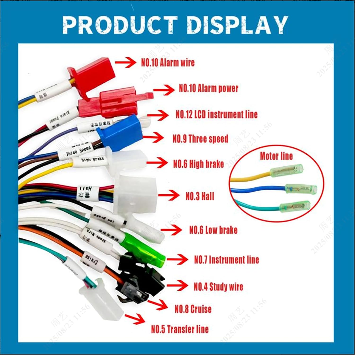
Figure 5.1: Wiring diagram for the brushless motor speed controller, showing various labeled connectors for alarm, power, LCD, speed, brake, Hall sensor, instrument line, study wire, and cruise functions.
General Wiring Guidelines:
- Power Connection: Connect the main power wires from your battery to the controller's power input. Ensure correct polarity (positive to positive, negative to negative).
- Motor Connection: Connect the three motor phase wires (typically green, blue, yellow) from your brushless motor to the corresponding outputs on the controller.
- Hall Sensor Wires: Connect the Hall sensor wires from your motor to the controller's Hall input. These are typically five smaller wires.
- Throttle Connection: Connect the three-wire throttle to the designated throttle input on the controller.
- Brake Levers: Connect the brake lever wires to the high/low electrical level brake inputs.
- Other Connections: Connect any additional wires for features such as alarm, LCD display, three-speed control, instrument line, study wire, or cruise function as per your specific setup and the diagram.
Ensure all connections are secure and insulated to prevent short circuits. Double-check all wiring before applying power.
6. Operating Instructions
Once the controller is correctly installed and all connections are secure, you can begin operation:
- Power On: Turn on the main power switch of your electric bicycle or scooter. The controller will initialize.
- Throttle Control: Gently twist the throttle to accelerate. The controller provides sensitive and steady speed control.
- Braking: Engage the brake levers to activate the braking function. The controller will cut power to the motor and apply braking based on the electrical level input.
- Speed Modes (if applicable): If your setup includes a three-speed switch, use it to cycle through different speed modes.
- Cruise Function (if applicable): If connected, activate the cruise function as per your vehicle's specific instructions.
Always operate your vehicle safely and in accordance with local regulations.
7. Maintenance
To ensure the longevity and optimal performance of your brushless motor speed controller, follow these maintenance guidelines:
- Keep Dry: Protect the controller from water and excessive moisture. While the aluminum casing offers some protection, it is not fully waterproof.
- Clean Regularly: Periodically clean the exterior of the controller to remove dust and debris. Use a soft, dry cloth. Do not use harsh chemicals or abrasive cleaners.
- Inspect Connections: Regularly check all wire connections for looseness or corrosion. Secure any loose connections and clean any corroded terminals.
- Avoid Overheating: Ensure the controller has adequate airflow, especially during prolonged use, to facilitate heat dissipation. The groove design of the aluminum shell aids in this.
- Storage: If storing the vehicle for an extended period, disconnect the battery from the controller. Store in a cool, dry place.
8. Troubleshooting
If you encounter issues with your controller, consider the following:
- No Power/No Response:
- Check battery charge level.
- Verify all power connections are secure and correctly polarized.
- Ensure the main power switch is on.
- Motor Not Spinning/Erratic Operation:
- Confirm the controller is only used with a three-wire brushless motor.
- Check the Hall sensor connections.
- Verify the three motor phase wires are correctly connected.
- Ensure the throttle is a three-wire type and correctly connected.
- Braking Issues:
- Check brake lever connections to the controller.
- No Reverse Function:
- Note that this controller, particularly low-power versions, does not support a reverse function. This is not a malfunction.
- LCD Display Not Working/Incompatible:
- This controller does not support professional and complex LCD equipment expansion. Ensure your display is compatible or use without one if not required.
If issues persist after troubleshooting, consult a qualified technician.
9. Important Notes and Warnings
- This controller is designed exclusively for three-wire brushless motors and three-wire throttles. Incompatibility with other motor or throttle types may lead to malfunction.
- Low power versions of this product do not include a reverse function.
- This controller is not designed to support advanced or complex LCD display systems.
- Always disconnect power before performing any installation, maintenance, or inspection.
- Do not attempt to modify the controller. Unauthorized modifications can void the warranty and pose safety risks.
- Ensure the controller is installed in a location that allows for adequate ventilation to prevent overheating.
10. Product Overview
Here are additional views of the Silscvtt Brushless Motor Speed Controller, highlighting its design and various components.

Figure 10.1: Front view of the Silscvtt Brushless Motor Speed Controller, showcasing its aluminum casing and the array of colored wires for various connections.

Figure 10.2: View of the controller with its key dimensions: length (4.09 inches), width (2.83 inches), and height (1.65 inches).

Figure 10.3: An overview of the controller along with close-ups of the different types of connectors and plugs used for various functions.


