1. Introduction
The ArecaIoT BSR02-DO02B is a 2-channel relay output module designed for industrial control and data acquisition applications. It features RS485 and RS232 communication interfaces, supporting the Modbus RTU protocol. This module allows for remote control of two independent relay outputs, making it suitable for various automation tasks.
2. Product Overview
The BSR02-DO02B module provides reliable relay switching capabilities with robust communication options. Key features include:
- 2 independent relay outputs, normally open configuration.
- Load capacity: 250V/2A per relay.
- Wide power supply range: DC9-48V.
- Communication interfaces: RS485 and RS232.
- Protocol support: Modbus RTU.
- Installation options: DIN rail mounting or screw fixing.
- Operating environment: -40°C to 70°C, 5% to 85% RH (non-condensing).

Figure 1: Front view of the ArecaIoT BSR02-DO02B module, showing terminal blocks for power, RS485, RS232, and the two relay outputs (Out1, Out2).
3. Specifications
| Feature | Specification |
|---|---|
| Model | BSR02-DO02B |
| Relay Outputs | 2 Channels, Normally Open |
| Load Capacity | 250V/2A per channel |
| Power Supply | DC9-48V |
| Communication Ports | RS485, RS232 |
| Communication Protocol | Modbus RTU |
| Installation | DIN rail mounting or screw fixing |
| Working Environment Temperature | -40°C to 70°C |
| Working Environment Humidity | 5% to 85% RH (non-condensing) |
| Manufacturer | ComWinTop |
| Country of Origin | China |

Figure 2: Approximate dimensions of a similar BSR series module (BSR-AD20B shown), indicating typical size for the BSR02-DO02B. Dimensions are approximately 95mm (height) x 50mm (width) x 32mm (depth).
4. Setup
4.1 Installation
The BSR02-DO02B module supports two installation methods:
- DIN Rail Mounting: Attach the module to a standard DIN rail using the integrated clip on the back.
- Screw Fixing: Use screws through the mounting holes located at the corners of the module to secure it to a flat surface.
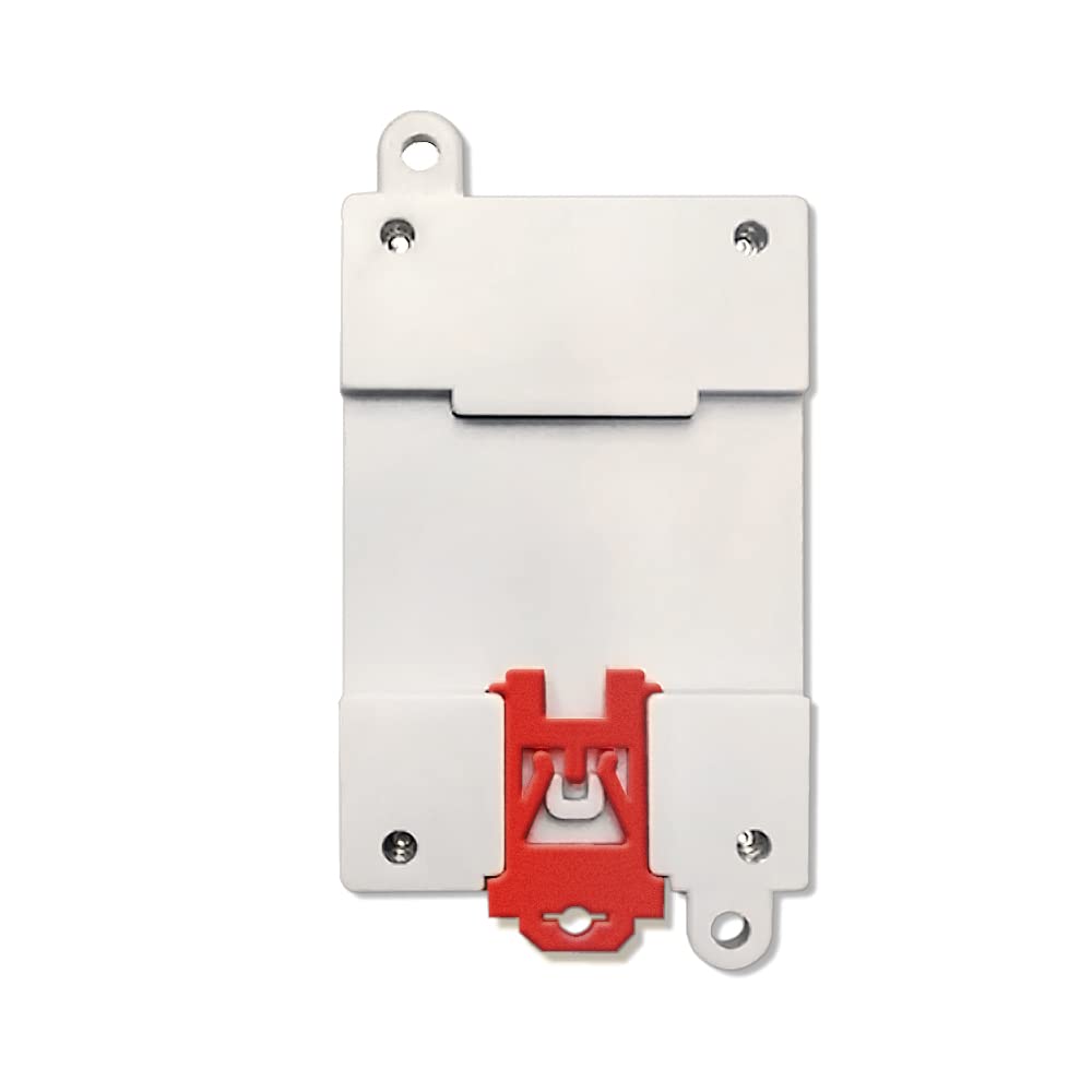
Figure 3: Back view of the module, illustrating the integrated red clip for DIN rail mounting.
4.2 Wiring
Ensure all power is disconnected before performing any wiring. Refer to the terminal labels on the module for correct connections.
4.2.1 Power Supply Connection
- Connect the positive (+) terminal of your DC9-48V power supply to the VCC terminal.
- Connect the negative (-) terminal of your DC power supply to the GND terminal.
4.2.2 RS485 Communication Connection
- Connect the RS485 A line to the module's A terminal.
- Connect the RS485 B line to the module's B terminal.
- Ensure proper termination resistors are used in the RS485 network if required.
4.2.3 RS232 Communication Connection
- Connect the RS232 RXD line from your device to the module's RXD terminal.
- Connect the RS232 TXD line from your device to the module's TXD terminal.
- Connect the RS232 GND line from your device to the module's GND terminal.
4.2.4 Relay Output Connection
The module provides two independent normally open (NO) relay outputs, labeled Out1 and Out2. Each output has two terminals: COM (Common) and NO (Normally Open).
- For Out1: Connect the load to the COM1 and NO1 terminals.
- For Out2: Connect the load to the COM2 and NO2 terminals.
- Ensure the connected load's voltage and current do not exceed the relay's maximum rating (250V/2A).
5. Operating Instructions
The BSR02-DO02B module communicates using the Modbus RTU protocol. A Modbus master device (e.g., PLC, HMI, PC with Modbus software) is required to control the relay outputs.
5.1 Modbus RTU Basics
The module acts as a Modbus RTU slave. Each module has a unique slave address (typically configurable via software or DIP switches, refer to specific software documentation for this model). Communication parameters such as baud rate, data bits, stop bits, and parity must match between the master and slave devices.
5.2 Controlling Relay Outputs
Relay outputs are typically controlled by writing to specific Modbus coil registers or holding registers. Consult the detailed Modbus register map provided by ArecaIoT for the BSR02-DO02B module. Generally:
- To turn a relay ON, write a '1' (or equivalent) to its corresponding coil/register address.
- To turn a relay OFF, write a '0' (or equivalent) to its corresponding coil/register address.
Example Modbus Function Codes (common for controlling outputs):
- Function Code 05 (Write Single Coil): Used to force a single coil (relay) ON or OFF.
- Function Code 15 (Write Multiple Coils): Used to force a series of coils (relays) ON or OFF.
- Function Code 06 (Write Single Register): May be used if relays are mapped to holding registers.
Refer to the Modbus RTU specification and the module's specific register map for precise addressing and control commands.
6. Maintenance
The BSR02-DO02B module is designed for reliable operation with minimal maintenance. However, periodic checks can help ensure longevity and performance.
- Cleaning: Keep the module free from dust and debris. Use a soft, dry cloth for cleaning. Do not use liquid cleaners or solvents.
- Environmental Conditions: Ensure the module operates within the specified temperature and humidity ranges. Avoid exposure to corrosive gases, excessive vibration, or direct sunlight.
- Wiring Integrity: Periodically inspect wiring connections for tightness and signs of wear or corrosion. Re-tighten terminal screws if necessary.
7. Troubleshooting
If you encounter issues with the BSR02-DO02B module, consider the following troubleshooting steps:
7.1 No Power Indication
- Check Power Supply: Verify that the DC9-48V power supply is connected correctly to the VCC and GND terminals and is providing the correct voltage.
- Wiring: Ensure power supply wires are securely connected and not damaged.
7.2 Communication Errors
- Wiring: Check RS485 (A/B) or RS232 (RXD/TXD/GND) connections for correctness and secure contact.
- Modbus Parameters: Confirm that the Modbus master's baud rate, data bits, stop bits, and parity settings match the module's configuration.
- Slave Address: Verify that the module's Modbus slave address is correctly set and unique within the network.
- Termination Resistors (RS485): Ensure proper termination resistors are used at the ends of the RS485 bus.
- Cable Length: For long communication lines, ensure appropriate cable types and lengths are used according to RS485/RS232 standards.
7.3 Relay Not Switching
- Communication: First, ensure communication with the module is established (see 7.2).
- Modbus Command: Verify that the correct Modbus command (function code, address, value) is being sent to control the desired relay.
- Load Connection: Check the wiring of the load to the COM and NO terminals.
- Load Rating: Ensure the connected load does not exceed the relay's maximum voltage and current ratings (250V/2A). Overloading can damage the relay.
8. Warranty and Support
ArecaIoT products are manufactured to high-quality standards. For warranty information, technical support, or service inquiries, please contact your vendor or the manufacturer directly. Keep your purchase receipt as proof of purchase.
Manufacturer: ComWinTop