1. Introduction
The U.S. Solid Water Leak Detector System is designed to provide reliable water leak detection and automatic shut-off functionality for your property. This system includes a motorized ball valve, a central controller, and three water leak sensors to help prevent water damage by detecting leaks and automatically closing the water supply.
2. Product Features
- Property Protection: Designed to monitor for water leaks, ensuring property safety. Features IP65 waterproof rating and a long lifespan.
- Automatic Shut-Off: Equipped with a motorized ball valve that automatically closes the water supply when a leak is detected.
- Multiple Sensors: Includes three leak detection sensors, each 19.69 feet long, for extensive coverage. Sensors send an immediate signal to the controller upon detecting water.
- Integrated Sound Alarm: An audible alarm notifies you immediately of any leaks. The alarm continues until the leakage is addressed and the system is reset.
- Central Controller: The system includes a controller that manages the sensors and the motorized valve, allowing for effective and timely leak prevention.
3. Package Contents
Verify that all components are present in the package:
- 1 x Motorized Ball Valve (1-inch, Stainless Steel)
- 1 x Controller
- 3 x Water Leak Sensors
- 1 x Power Adapter (Charger)
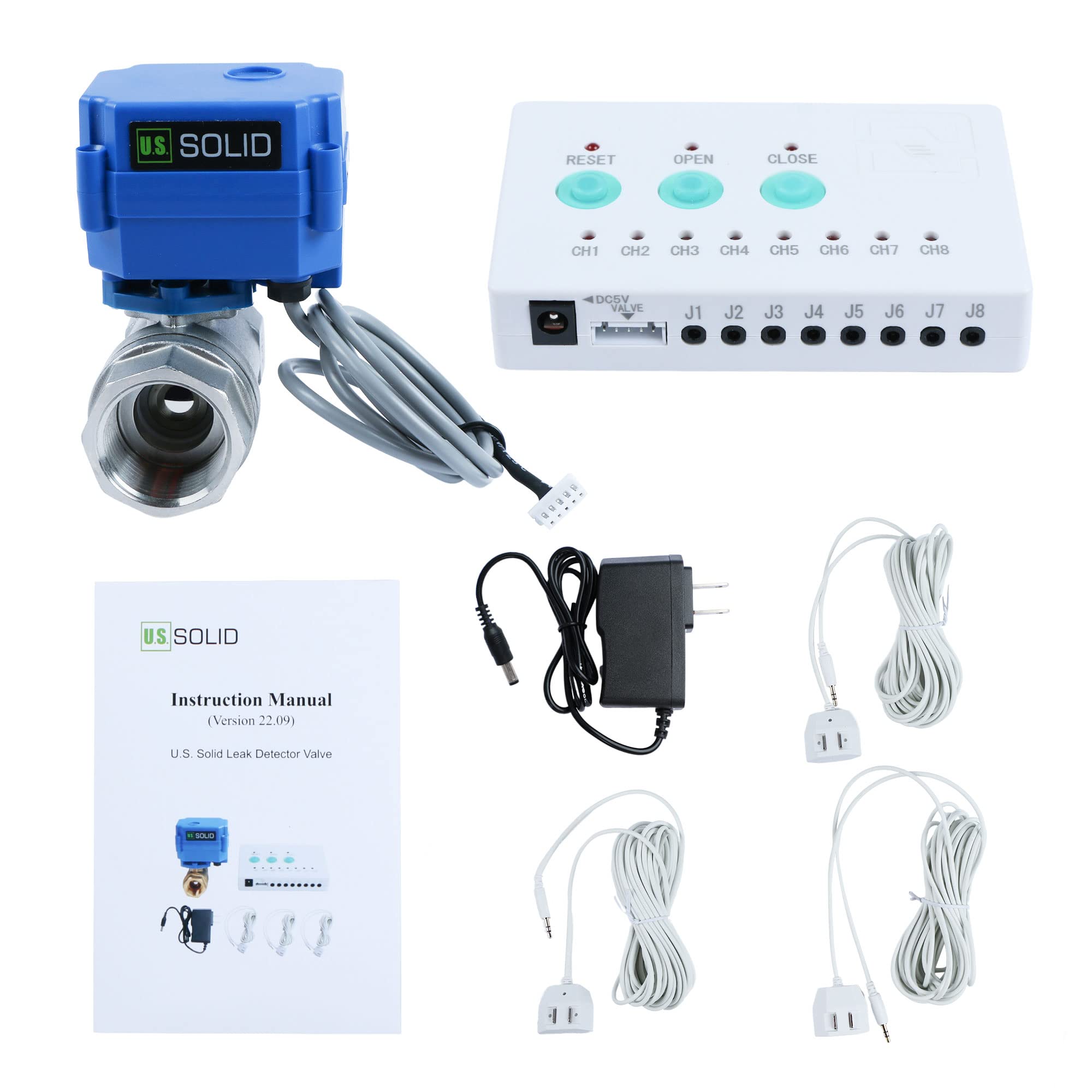
Image: All components of the U.S. Solid Water Leak Detector System, including the motorized valve, controller, three sensors, and power adapter.
4. Specifications
| Specification | Value |
|---|---|
| Model Number | USS-LDV00009 |
| Material | Stainless Steel |
| Valve Size | 1 inch |
| Mounting Type | Tabletop or Free-standing |
| Sensor Technology | Flow Sensor |
| Item Weight | 0.99 Kilograms (2.18 pounds) |
| Product Dimensions | 4.3 x 4.9 x 3.5 inches |
| Voltage | 5 Volts |
| Power Source | Corded Electric |
| Ingress Protection (IP) Rating | IP65 (Dust tight, protected from water jets) |

Image: Dimensions of the motorized ball valve component.

Image: Explanation of IP65 rating and visual representation of Normally Closed/Open and Full/Standard Port valve types.
5. Safety Information
- Read all instructions carefully before installation and operation.
- Ensure the power supply matches the specified voltage (5V).
- Do not immerse the controller or power adapter in water. The valve and sensors are designed for water contact, but the main control unit is not.
- Installation of the motorized valve should be performed by a qualified individual if you are unsure about plumbing procedures.
- Keep out of reach of children.
6. Setup and Installation
6.1. Motorized Ball Valve Installation
Install the motorized ball valve onto your main water pipeline or the specific pipeline you wish to monitor. Ensure the valve is installed in the correct flow direction. For a watertight seal, apply Teflon tape to the male pipe threads before screwing the valve firmly into place.

Image: The motorized ball valve in a closed position, ready for installation.

Image: The motorized ball valve in an open position, showing the internal flow path.
6.2. Sensor Placement
Place the three water leak sensors in areas prone to leaks, such as near water heaters, washing machines, sinks, toilets, or in basements. The sensors are designed to detect water on their metal contacts.

Image: A single water leak sensor with its detection contacts.
6.3. Connecting Components to the Controller
Connect the motorized ball valve, the three sensors, and the power adapter to the controller as follows:
- Connect the motorized ball valve's cable to the "DC5V VALVE" port on the controller.
- Plug each of the three sensors into any of the available "J1" through "J8" ports on the controller.
- Connect the power adapter to the controller's power input port and then plug the adapter into a standard electrical outlet.

Image: Side view of the controller showing the "DC5V VALVE" port, sensor input jacks (J1-J8), and power input.

Image: The power adapter used to supply power to the controller.
6.4. Setup Video Guide
For a visual guide on the setup process, please refer to the following video:
Video: A detailed guide demonstrating the installation of the motorized ball valve, placement of sensors, and connection of all components to the controller.
7. Operation
7.1. Initial Valve Operation
After connecting all components and powering on the controller, you can manually operate the valve using the buttons on the controller:
- Press the "OPEN" button to open the motorized ball valve, allowing water flow.
- Press the "CLOSE" button to close the motorized ball valve, stopping water flow.
Once the valve is opened, the system is active and ready to detect leaks.

Image: Top view of the controller showing the 'RESET', 'OPEN', and 'CLOSE' buttons, along with channel indicator lights.
7.2. Leak Detection and Alarm
When a water leak is detected by any of the connected sensors, the controller will automatically initiate the following actions:
- The motorized ball valve will automatically close, shutting off the water supply.
- An audible alarm will sound from the controller to alert you of the leak.
- The corresponding channel indicator light (CH1-CH8) for the activated sensor will illuminate.
7.3. Resetting the System After a Leak
To stop the alarm and restore water flow after a leak has been detected and addressed:
- Clean up the detected leakage from the sensor.
- Press the "RESET" button on the controller to silence the alarm.
- Press the "OPEN" button to reopen the motorized ball valve and restore water flow.
8. Maintenance
- Sensor Cleaning: Periodically inspect the water leak sensors for dust or debris on their metal contacts. Clean with a dry cloth if necessary to ensure proper function.
- System Testing: It is recommended to test the system periodically (e.g., monthly) by placing a small amount of water on a sensor to confirm the alarm and automatic shut-off functions are working correctly.
- Valve Inspection: Check the motorized valve for any signs of wear or leakage around the connections.
- Controller Care: Keep the controller in a dry environment, away from direct sunlight and extreme temperatures.
9. Troubleshooting
| Problem | Possible Cause | Solution |
|---|---|---|
| System does not power on. | Power adapter not connected or faulty. | Ensure power adapter is securely plugged into the controller and a working outlet. Test the outlet with another device. |
| Valve does not open/close manually. | Valve cable loose or faulty; power issue. | Check the connection of the valve cable to the controller. Ensure the controller is powered. |
| No alarm when water is detected. | Sensor not connected; sensor contacts dirty; alarm malfunction. | Ensure sensors are securely plugged into the controller. Clean sensor contacts. Test with a different sensor if available. |
| False alarms. | Sensor contacts are wet or dirty. | Ensure sensor contacts are completely dry and clean. Relocate sensor if it's in a high-humidity area causing condensation. |
| Valve does not reopen after a leak. | System not reset; residual water on sensor. | Ensure all water is removed from the sensor and press the "RESET" button before pressing "OPEN". |
10. Warranty and Support
U.S. Solid offers a 1-year warranty or money-back promise for this product, ensuring customer satisfaction. For technical support, troubleshooting assistance, or warranty claims, please contact U.S. Solid customer service through the retailer where the product was purchased or visit the official U.S. Solid website.
Manufacturer: U.S. Solid
GTIN (UPC): 888107104735


