Lutema LTMKIT-Hisense-75R6E4-1013
Lutema Television Repair Kit for Hisense 75R6E4
Installation and Compatibility Guide
1. Introduction
This instruction manual provides essential information for the proper installation and use of the Lutema Television Repair Kit for Hisense 75R6E4 televisions. This kit is designed to replace key internal components, including the Main Board, Power Supply, and T-Con Board, to restore functionality to your television. It is intended for individuals with basic knowledge of electronics and television repair procedures.
2. Important Safety Information
Before proceeding with any repair, please read and understand the following safety precautions:
- Disconnect Power: Always unplug the television from the main power outlet before opening the back cover or handling any internal components.
- Static Electricity: Electronic components are sensitive to static discharge. Use an anti-static wrist strap or frequently touch a grounded metal object to discharge static electricity from your body.
- Professional Assistance: If you are unsure about any step or lack experience with electronics repair, it is highly recommended to seek assistance from a qualified technician.
- Component Handling: Handle all circuit boards and components by their edges to avoid damaging sensitive parts.
- Capacitors: Power supply boards may contain large capacitors that can store a dangerous electrical charge even after being unplugged. Exercise extreme caution.
3. Kit Contents
The Lutema Television Repair Kit typically includes the following components. Specific parts may vary based on the television's panel version:
- Main Board: The primary control unit of the television.
- Power Supply Board: Regulates and distributes power to all TV components.
- T-Con Board (Timing Controller): Processes video signals for the display panel.
- WiFi Module: For wireless network connectivity (if applicable and separate).
- IR Sensor: For remote control reception (if applicable and separate).
- Associated Cables: Major flex cables and wires for connecting components.

Image 3.1: Overview of the Lutema Television Repair Kit, showing the main board, power supply, T-Con board, and smaller modules.
4. Compatibility and Panel Matching
IT IS CRITICAL TO MATCH YOUR TELEVISION'S OPEN CELL (LCD PANEL NUMBER) WITH THE LISTED COMPATIBLE PANELS BELOW BEFORE ORDERING OR INSTALLING. Failure to select the matching panel number could result in a software mismatch or incompatibility.
The same television model may have different internal components depending on its manufacturing date and factory. Therefore, relying solely on the TV's make and model is insufficient. Please locate your TV's Open Cell/Panel Number, typically found on a sticker on the back of the LCD panel itself, and compare it to the following list:
Compatible Panel Versions and Corresponding Boards:
Open Cell/Panel: HV750QUB-F91
- Main Board: RSAG7.820.11135/ROH, RSAG7.820.8333/ROH
- T-Con Board: RSAG7.820.11320/ROH
- Power Supply: RSAG7.820.10689/ROH, RSAG7.820.9863/R0H, 267224
- WiFi Module: ZDRK8812CU, 22470-RK8812CU, 1250667
- IR Sensor: RSAG7.820.8441/ROH
Open Cell/Panel: HV750QUB-F90
- Main Board: 289605B, 289604B
- T-Con Board: 283051, 289127
- Power Supply: 302334, RSAG7.820.10689/ROH
- WiFi Module: 1250667, 2AJVQ-RK8812CU
- IR Sensor: 294501 MZMH1, RSAG7.820.8441/ROH
Open Cell/Panel: HV750QUB-F91 1
- Main Board: 311981B, RSAG7.820.11722/ROH
- T-Con Board: RSAG7.820.12014/ROH, 308271
- Power Supply: 318214, RSAG7.820.10689/ROH
- WiFi Module: 1250667, 22470-RK8812CU
- IR Sensor: RSAG7.820.8441
Open Cell/Panel: JR745R3HC5Y
- Main Board: RSAG7.820.11722/ROH, 75R6E4
- T-Con Board: RSAG7.820.13242/ROH
- Power Supply: RSAG7.820.11820/ROH, E166702
- WiFi Module: 1250667, 22470-RK8812CU
- IR Sensor: RSAG7.820.12653/ROH
Open Cell/Panel: HV750QUB-F90 1
- Main Board: RSAG7.820.9794/ROH, E248779
- T-Con Board: RSAG7.820.9959/ROH
- Power Supply: RSAG7.820.9863/ROH, E56327
- WiFi Module: WC0HR2601
- IR Sensor: E193079
5. Installation/Setup
The following steps provide a general overview of the installation process. Specific disassembly and reassembly procedures may vary by television model. Always refer to your television's service manual for detailed instructions if available.
- Prepare the Work Area: Ensure a clean, well-lit, and static-free workspace. Place the television face down on a soft, protective surface to prevent screen damage.
- Remove Back Cover: Carefully remove all screws securing the television's back cover. Gently detach the cover, being mindful of any connected cables (e.g., for control buttons or IR sensor).
- Identify Components: Locate the Main Board, Power Supply Board, and T-Con Board within your television. Compare them to the components in your repair kit.
- Disconnect Cables: Carefully disconnect all cables connected to the boards you intend to replace. Pay attention to their orientation and connection points. It is advisable to take photos for reference.
- Remove Old Boards: Unscrew and gently remove the faulty boards from the television chassis.
- Install New Boards: Place the new boards from the kit into their respective positions. Secure them with the original screws.
- Reconnect Cables: Reconnect all cables to the new boards, ensuring they are seated correctly and securely. Double-check all connections.
- Initial Test: Before replacing the back cover, temporarily plug in the TV and power it on to verify basic functionality (e.g., screen illumination, power indicator). If issues arise, immediately unplug and recheck connections.
- Reassemble: Once functionality is confirmed, unplug the TV, replace the back cover, and secure all screws.

Image 5.1: Front view of a typical Main Board, showing input/output ports and processing chips.

Image 5.2: Back view of the Main Board, illustrating the complex circuit traces.
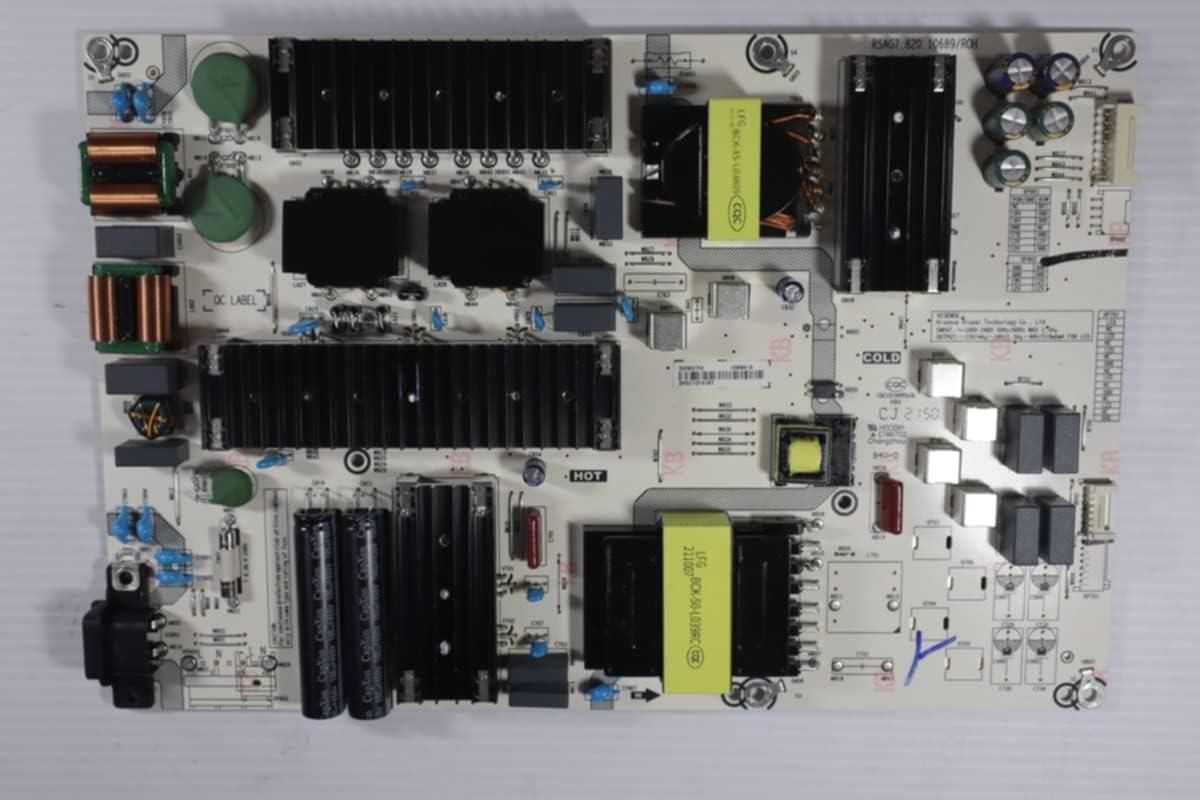
Image 5.3: Front view of a typical Power Supply Board, featuring large capacitors and transformers.

Image 5.4: Back view of the Power Supply Board, showing solder points and circuit paths.

Image 5.5: Front view of a typical T-Con Board, featuring connectors for ribbon cables that connect to the LCD panel.
6. Operating
After successful installation of the repair kit, your Hisense 75R6E4 television should operate as intended. Power on the TV using the remote control or the power button on the television itself. Proceed with any initial setup steps or channel scanning as required by your television model.
7. Maintenance
The components in this repair kit are designed for long-term reliability and generally require no specific maintenance after installation. To ensure the longevity of your television and its new components:
- Keep the television in a well-ventilated area to prevent overheating.
- Avoid exposing the television to excessive dust, moisture, or extreme temperatures.
- Clean the exterior of the television regularly with a soft, dry cloth. Do not use harsh chemicals or abrasive cleaners.
8. Troubleshooting
If you encounter issues after installing the repair kit, consider the following troubleshooting steps:
- No Power: Ensure the power cable is securely plugged into both the TV and the wall outlet. Check the power supply board connections.
- No Picture/Sound: Verify all internal ribbon cables and connectors are firmly seated. Check external input sources and cables.
- Distorted Picture: Recheck the T-Con board connections, especially the ribbon cables to the LCD panel. Ensure the correct panel version was matched during purchase.
- Remote Not Working: Check the IR sensor connection and ensure there are no obstructions. Replace remote batteries.
- Software Mismatch: If the panel number was not correctly matched, a software incompatibility may occur. In this case, the kit may not be suitable for your television.
- Seek Professional Help: If problems persist after basic troubleshooting, consult a qualified television repair technician.
9. Specifications
| Feature | Detail |
|---|---|
| Product Model Number | LTMKIT-Hisense-75R6E4-1013 |
| Compatible TV Model | Hisense 75R6E4 (with matching panel number) |
| Kit Components | Main Board, Power Supply, T-Con, WiFi Module, IR Sensor, Cables |
| Item Weight | 12 ounces |
| Product Dimensions | 4 x 5 x 1 inches (packaging) |
| Connectivity Technology | Bluetooth, Wi-Fi (via included modules) |
| Display Type Compatibility | LCD, LED |
10. Warranty and Support
This Lutema Television Repair Kit comes with a 30-Day Warranty from the date of purchase. Our replacement kits are sourced from working televisions and are tested to be 100% functional. All parts are marked with tamper-proof stickers and stamps to ensure quality.
If you require assistance in locating the correct parts for your device or have questions regarding installation, our specialists are available to provide support. Please contact Lutema customer service for further assistance.