1. Introduction
This manual provides detailed instructions for the installation, operation, and maintenance of the Generic Alan Mixer GLD80 170MM with B10K 4 Foot Motor Fader Potentiometer 8MMT. Please read this manual thoroughly before using the product to ensure proper function and longevity.
This component is designed for integration into audio mixing consoles, specifically the Alan Mixer GLD80, serving as a motorized fader potentiometer. It provides precise control over audio levels and features a B10K resistance value and an 8MMT shaft for compatibility.
2. Product Overview

This image shows a close-up, magnified view of the Alan Mixer GLD80 170MM motor fader potentiometer. The text "ALPS Alan mixer GLD80 170MM B10K 8MMT" is visible, indicating the model and specifications of the component. This view emphasizes the precision and detailed markings on the fader.

This image displays a side view of the Alan Mixer GLD80 170MM motor fader potentiometer. It clearly shows the elongated fader body, the integrated motor mechanism on one end, and the potentiometer contacts on the other. The overall length of the unit is evident, indicating its 170mm dimension.

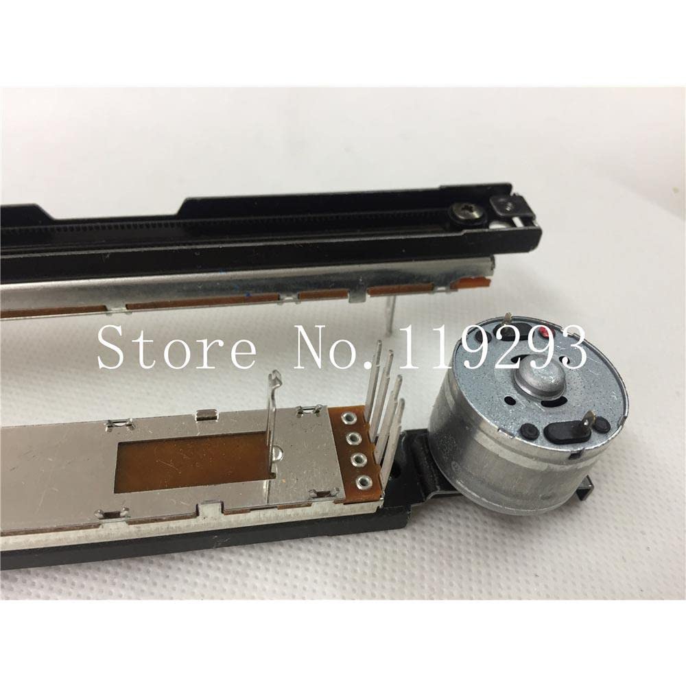
An angled perspective of the Alan Mixer GLD80 170MM motor fader potentiometer is presented here. This view allows for observation of both the upper track assembly and the lower potentiometer board, providing a comprehensive look at the component's construction and how the motor integrates with the fader mechanism.

This image provides another angled view of the Alan Mixer GLD80 170MM motor fader potentiometer, specifically focusing on the electrical connection pins. The pins are clearly visible, indicating where the fader would be soldered or connected to a circuit board within the mixer. The '525C 10KB' marking on the potentiometer is also discernible.
A close-up shot of the motor end of the Alan Mixer GLD80 170MM motor fader potentiometer. This view highlights the compact motor housing and the small gear mechanism responsible for driving the fader's movement. The precision engineering of the motor assembly is visible, crucial for smooth and accurate fader operation.

This image provides a detailed close-up of the potentiometer end of the Alan Mixer GLD80 170MM motor fader. The multiple contact pins are clearly visible, along with the underlying circuit board where the resistive track is located. The 'ALPS' branding is also discernible on the metal casing, indicating the manufacturer of the potentiometer component.
3. Setup and Installation
This fader is an internal component and requires professional installation within a compatible audio mixing console. Improper installation can lead to damage to the fader or the mixer.
3.1 Safety Precautions
- Ensure the mixer is powered off and disconnected from all power sources before beginning installation.
- Wear anti-static wrist straps to prevent electrostatic discharge (ESD) damage to sensitive electronic components.
- Use appropriate tools for disassembly and reassembly of the mixer.
- Refer to the specific service manual of your Alan Mixer GLD80 for detailed disassembly and reassembly procedures.
3.2 Installation Steps
- Carefully open the Alan Mixer GLD80 chassis according to its service manual.
- Locate the fader assembly that needs replacement or installation.
- Desolder the existing fader (if replacing) from the circuit board, noting the orientation of the pins.
- Align the new GLD80 170MM motor fader potentiometer with the corresponding holes on the circuit board. Ensure the motor and shaft orientation are correct.
- Solder the fader pins securely to the circuit board. Ensure all solder joints are clean and strong.
- Carefully reassemble the mixer chassis, ensuring all screws are tightened and connections are secure.
4. Operating Instructions
Once installed, the motor fader operates as an integral part of the Alan Mixer GLD80's control surface. Its primary function is to provide precise, motorized control over audio channel levels or other assigned parameters.
4.1 Manual Operation
The fader can be moved manually by hand to adjust the corresponding parameter. The B10K potentiometer provides a logarithmic resistance curve suitable for audio level control.
4.2 Motorized Operation
The integrated motor allows the fader to automatically move to a position commanded by the mixer's internal automation system or external control signals (e.g., MIDI, DAW automation). This feature is crucial for recalling scenes, automating mixes, and maintaining precise level synchronization.
- Ensure the mixer's automation features are enabled and configured correctly.
- Observe the fader's movement during automated playback to confirm proper function.
- Avoid forcing the fader manually against strong motor resistance, as this may damage the motor or gears.
5. Maintenance
Proper maintenance ensures the longevity and reliable performance of the motor fader.
5.1 Cleaning
- Keep the fader slot on the mixer clean and free of dust and debris.
- Use a soft, dry, lint-free cloth to wipe the fader knob and surrounding area.
- For internal cleaning (only if necessary and by qualified personnel), use compressed air to gently remove dust from the fader track and motor assembly. Avoid using liquid cleaners directly on the fader mechanism.
5.2 Lubrication
The fader mechanism is typically pre-lubricated. Avoid applying additional lubricants unless specifically recommended by the mixer manufacturer's service manual. Improper lubricants can attract dust and degrade performance.
5.3 Inspection
Periodically inspect the fader for smooth operation. If you notice any grinding, sticking, or inconsistent movement, consult a qualified service technician.
6. Troubleshooting
This section addresses common issues that may arise with the motor fader.
| Problem | Possible Cause | Solution |
|---|---|---|
| Fader not moving or erratic movement (motorized) |
|
|
| No audio level change or intermittent audio |
|
|
| Fader feels stiff or gritty |
|
|
For issues not listed here, or if the suggested solutions do not resolve the problem, please contact a qualified service technician or the manufacturer of your Alan Mixer GLD80.
7. Specifications
| Parameter | Value |
|---|---|
| Model | GLD80 170MM Motor Fader Potentiometer |
| Resistance Value | B10K (10 kOhm, Linear Taper) |
| Fader Length | 170MM |
| Shaft Type | 8MMT (8mm diameter, specific type) |
| Type | Motorized Fader Potentiometer |
| Compatibility | Designed for Alan Mixer GLD80 (and potentially other compatible systems) |
8. Warranty and Support
As this product is a component part, its warranty is typically covered under the warranty of the complete system (e.g., the Alan Mixer GLD80) into which it is installed, or by the reseller. Please refer to your purchase documentation or contact the seller for specific warranty information.
For technical support regarding the installation or function of this component, it is recommended to consult the service manual for your Alan Mixer GLD80 or contact a qualified audio equipment technician.