1. Introduction
This manual provides comprehensive instructions for the safe and effective use of the Hantek DSO2C10 Digital Storage Oscilloscope. It covers essential information regarding product setup, operation, maintenance, and troubleshooting. Please read this manual thoroughly before operating the device to ensure proper functionality and to prevent damage or injury.
2. Safety Information
Always observe the following safety precautions to prevent electric shock, fire, or personal injury, and to ensure the longevity of the instrument.
- Power Source: Connect the oscilloscope only to a power source that matches the voltage and frequency specifications indicated on the rear panel.
- Grounding: Ensure the oscilloscope is properly grounded using the supplied power cord. Do not defeat the grounding feature.
- Probes: Use only probes rated for the voltage and current levels being measured. Ensure probes are in good condition and properly connected.
- Environment: Operate the device in a dry, well-ventilated area. Avoid exposure to moisture, dust, direct sunlight, or extreme temperatures.
- Servicing: Do not attempt to service the instrument yourself. Refer all servicing to qualified personnel. Hazardous voltages are present inside the device.
- Ventilation: Do not block the ventilation openings on the instrument.
WARNING:
Hazardous voltage inside. Do not remove the cover unless by specified personnel.
3. Product Overview
The Hantek DSO2C10 is a 2-channel digital storage oscilloscope with a 100MHz bandwidth and 1GSa/s real-time sample rate. It features an 8M memory depth and a 7-inch TFT LCD display for clear waveform visualization. This section details the physical components and included accessories.
3.1 Front Panel

Figure 3.1: Front view of the Hantek DSO2C10 Oscilloscope, showing the display, control knobs, function buttons, and input channels.
The front panel includes the main display, various control knobs for vertical and horizontal adjustments, trigger settings, and function buttons for menu navigation, measurement, utility, and more. Input channels CH1 and CH2 are located at the bottom right, along with the external trigger/generator output.
3.2 Rear Panel

Figure 3.2: Rear view of the Hantek DSO2C10 Oscilloscope, displaying the power input, ventilation, and USB ports.
The rear panel houses the power input connector, ventilation grilles, and USB ports for data transfer and firmware updates. A handle is integrated for portability.
3.3 Included Accessories

Figure 3.3: Standard accessories included with the Hantek DSO2C10, such as probes, power cord, and USB cable.
The standard package typically includes:
- Hantek DSO2C10 Digital Storage Oscilloscope unit
- Two passive probes (e.g., 100MHz 1X/10X switchable)
- Power cord
- USB cable
- BNC to Alligator Clip cable
- User Manual (digital copy on USB drive)
3.4 Probe Specifications (P4100 Example)

Figure 3.4: Example of a high voltage probe (P4100) that may be included or compatible with the DSO2C10.

Figure 3.5: Technical specifications for the P4100 probe, detailing attenuation, bandwidth, and voltage ratings.
The probes supplied with the oscilloscope are crucial for accurate measurements. Ensure the probe's attenuation setting (e.g., 1X or 10X) matches the setting on the oscilloscope for correct readings. The P4100 probe, for instance, offers a 100X attenuation ratio and is designed for high voltage applications up to 2000Vp.p.
4. Setup
Follow these steps to set up your Hantek DSO2C10 oscilloscope for initial use.
- Unpacking: Carefully remove the oscilloscope and all accessories from the packaging. Inspect for any signs of damage.
- Power Connection: Connect the supplied power cord to the AC input on the rear panel of the oscilloscope and then to a grounded power outlet.
- Power On: Press the power button located on the front panel to turn on the oscilloscope. The device will perform a self-test and display the main waveform interface.
- Probe Connection:
- Connect the BNC connector of a probe to one of the input channels (CH1 or CH2) on the front panel.
- Ensure the probe's attenuation switch (e.g., 1X/10X) is set to the desired ratio.
- Probe Compensation:
- Connect the probe tip to the probe compensation test point (usually a square wave output) on the front panel and the ground clip to the ground terminal.
- Adjust the compensation trimmer on the probe until a flat-top square wave is displayed on the screen. This ensures accurate signal reproduction.
5. Operating Instructions
This section covers the basic operation and key features of the DSO2C10 oscilloscope.
5.1 Basic Measurements
To perform a basic voltage and time measurement:
- Connect Probe: Connect a compensated probe to the signal source and the oscilloscope input channel.
- Auto Set: Press the AUTO SET button. The oscilloscope will automatically adjust vertical, horizontal, and trigger settings to display a stable waveform.
- Adjust Vertical Scale (VOLTS/DIV): Use the VOLTS/DIV knob for the active channel to adjust the vertical scale (voltage per division) to fit the waveform on the screen.
- Adjust Horizontal Scale (SEC/DIV): Use the SEC/DIV knob to adjust the horizontal scale (time per division) to view the desired number of cycles.
- Position Adjustment: Use the POSITION knobs for vertical and horizontal axes to move the waveform on the screen.
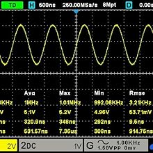
Figure 5.1: Example of a sine wave displayed with automatic measurements for frequency, peak-to-peak voltage, and other parameters.
5.2 Triggering
Triggering stabilizes repetitive waveforms and captures single-shot events. The DSO2C10 offers various trigger modes.
- Trigger Level: Use the TRIGGER LEVEL knob to set the voltage level at which the oscilloscope captures the waveform.
- Trigger Mode: Access trigger settings via the TRIGGER MENU button to select modes like Edge, Pulse, Video, Slope, etc.
- Trigger Source: Select the input channel (CH1, CH2, EXT) or the internal signal generator as the trigger source.
5.3 Advanced Features
- Arbitrary Waveform Output: The DSO2C10 supports arbitrary waveform output, allowing users to generate various test signals. Refer to the WAVE GEN section of the menu for configuration.
- Serial Protocol Triggers and Decodes: The device includes standard support for 5 kinds of serial protocol triggers and decodes, useful for debugging embedded systems and communication interfaces. Access these features through the DECODE menu.
- Memory Depth: With an 8M memory depth, the oscilloscope can capture longer signal durations at high sample rates, enabling detailed analysis of transient events.
- Measurement Functions: Utilize the MEASURE menu to display automatic measurements such as Vpp, Vmax, Vmin, Freq, Period, Rise Time, Fall Time, etc.
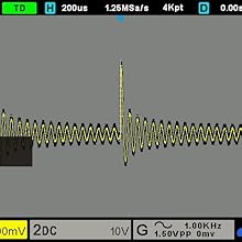
Figure 5.2: Example of serial protocol decoding on the oscilloscope display, showing data packets and timing.
6. Maintenance
Proper maintenance ensures the longevity and accuracy of your oscilloscope.
- Cleaning:
- Clean the exterior of the instrument with a soft, damp cloth. Do not use abrasive cleaners or solvents.
- Ensure the device is powered off and unplugged before cleaning.
- Storage:
- Store the oscilloscope in a cool, dry environment, away from direct sunlight and extreme temperatures.
- Protect the screen from scratches.
- Firmware Updates: Periodically check the Hantek official website for available firmware updates. Firmware updates can improve performance, add features, and fix bugs. Follow the instructions provided by Hantek carefully when performing updates.
- Probe Care: Handle probes carefully. Avoid bending cables sharply or exposing them to excessive force. Regularly inspect probes for damage.
7. Troubleshooting
This section addresses common issues you might encounter with your DSO2C10 oscilloscope.
| Problem | Possible Cause | Solution |
|---|---|---|
| No Power | Power cord not connected; Power outlet faulty; Device fuse blown. | Check power cord connection; Test power outlet; Contact service for fuse replacement. |
| No Waveform Displayed | Probe not connected; Input signal too small/large; Vertical/Horizontal scale incorrect; Trigger not set correctly. | Ensure probe is connected to signal and channel; Adjust VOLTS/DIV and SEC/DIV; Press AUTO SET; Adjust trigger level. |
| Unstable Waveform | Incorrect trigger settings; No stable trigger source. | Adjust trigger level; Change trigger mode; Ensure a stable signal is connected to the trigger source. |
| Device Locks Up / Unresponsive | Misconfigured settings; Software glitch. | Power off the device, wait a few seconds, then power back on. This often resolves temporary software issues. Review recent setting changes. |
| Inaccurate Measurements | Probe not compensated; Incorrect probe attenuation setting; Probe damaged. | Perform probe compensation; Ensure probe attenuation matches oscilloscope setting; Inspect probe for damage. |
If the problem persists after attempting these solutions, please contact Hantek customer support or a qualified service technician.
8. Specifications
The following are the key technical specifications for the Hantek DSO2C10 Digital Storage Oscilloscope.
- Model: DSO2C10 (TXD-a219)
- Bandwidth: 100 MHz
- Channels: 2 Analog Channels
- Real-time Sample Rate: 1 GSa/s
- Memory Depth: 8M points
- Display: 7-inch TFT LCD
- Arbitrary Waveform Output: Supported
- Serial Protocol Decode: 5 types supported
- Product Dimensions: 12.6 x 4.33 x 5.91 inches
- Product Weight: 4.2 Pounds
- Manufacturer: Hantek
- First Available: March 6, 2021
9. Warranty and Support
Hantek products are designed for reliability and performance. For warranty information, please refer to the documentation included with your purchase or visit the official Hantek website.
- Warranty: Standard manufacturer's warranty applies. Please retain your proof of purchase for warranty claims.
- Technical Support: For technical assistance, firmware updates, and additional resources, please visit the official Hantek website: www.hantek.com.
- User Manual: A digital copy of the detailed user manual and any supplementary guides can typically be found on the Hantek website.


