1. Introduction
This manual provides essential information for the safe and efficient operation of your Tbest AT2-1500X Variable Frequency Drive (VFD) speed controller. Please read this manual thoroughly before installation, operation, or maintenance to ensure proper use and prevent potential hazards.
The Tbest AT2-1500X VFD is designed for controlling the speed of single-phase AC motors up to 1.5 kW. It features a unique control method for high torque, precision, and a wide speed regulation range. Its robust design offers good anti-trip performance and adaptability to various environmental conditions, including power fluctuations, temperature, humidity, and dust interference. The VFD incorporates optimized PWM control technology and electromagnetic compatibility for low noise and reduced electromagnetic interference.
2. Safety Precautions
WARNING: Failure to follow these safety instructions may result in death, severe injury, or serious damage to the inverter.
- Always ensure the power supply is disconnected before performing any wiring or maintenance on the VFD.
- Do not touch the VFD terminals when power is applied, as this can cause severe damage to the inverter.
- Do not install the VFD in environments with flammable materials to avoid fire hazards.
- The ground terminal of the inverter must be properly and securely grounded.
- Avoid installing the VFD in environments with explosive gases to prevent explosion hazards.
- Only qualified personnel should perform internal inspections or repairs of the VFD. Incorrect procedures can lead to damage or injury.

Figure 1: Front view of the VFD showing the control panel and safety warning label.
3. Product Features
- High Performance: Utilizes a unique control method to achieve high torque, high precision, and a wide speed regulation range.
- Enhanced Stability: Features good anti-trip performance and adaptability to power fluctuations, temperature, humidity, and dust interference.
- Low Noise & EMI: Optimized PWM control technology and electromagnetic compatibility minimize operational noise and electromagnetic interference.
- User-Friendly Wiring: Easy to use and connect with screw terminals for convenient wiring.
- Efficient Heat Dissipation: Designed with a large heat sink to ensure effective heat dissipation and prolonged operational life.
4. Specifications
| Parameter | Value |
|---|---|
| Model | AT2-1500X |
| Application Range | Universal |
| Power Phase | Single Phase |
| Rated Current | 8 A |
| Rated Voltage | AC 220 V (Single Phase) |
| Supply Voltage | Low Voltage |
| Suitable Motor Power | 1.5 kW |
| Filter | None |
| DC Power Source Type | Current Type |
| Control Method | V/F Open-Loop Control |
| Adjustable Output Voltage Method | PWM Control |
| Dimensions (approx.) | 12.5 x 12.5 x 18 cm |
| Product Reference Number | Tbesth8d7koib43 |

Figure 2: Rear view of the VFD, highlighting cooling and terminal access.

Figure 3: Bottom view of the VFD, illustrating the heat sink design for efficient cooling.
5. Setup and Installation
Proper installation is crucial for the safe and reliable operation of the VFD. Ensure all safety precautions are followed before proceeding.
5.1 Mounting
- Mount the VFD in a clean, dry, and well-ventilated area, away from direct sunlight, excessive heat, moisture, and dust.
- Ensure sufficient clearance around the VFD for proper airflow, especially around the heat sink and cooling fans.
- Avoid mounting on flammable surfaces.
5.2 Wiring
All wiring must be performed by a qualified electrician and in accordance with local electrical codes.
- Power Input (L, N): Connect the single-phase AC 220V power supply to the 'L' and 'N' terminals.
- Motor Output (U, V, W): Connect the single-phase AC motor to the 'U', 'V', and 'W' terminals. For single-phase motors, typically two of these terminals are used, or specific wiring instructions for your motor should be followed.
- Ground (GND): Connect the ground terminal to a reliable earth ground. This is critical for safety.
- Control Terminals: The VFD includes additional control terminals for external control signals (e.g., start/stop, speed reference). Refer to the detailed wiring diagram for specific connections.

Figure 4: Detailed view of the VFD's screw terminals for electrical connections.
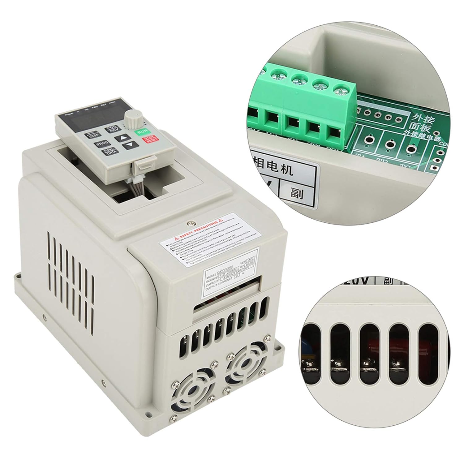
Figure 5: Overview of the VFD with a focus on the control panel and wiring interface.
6. Operating Instructions
The VFD features an intuitive control panel for easy operation.

Figure 6: Control panel of the Tbest AT2-1500X VFD.
6.1 Control Panel Overview
- Display: Shows operational parameters such as frequency, current, voltage, and speed.
- DISP Button: Cycles through different display parameters.
- FWD/REV Buttons: Controls the forward and reverse direction of the motor.
- PROG Button: Enters programming mode to adjust VFD parameters.
- FUNC/DATA Button: Used to select functions or confirm data entry in programming mode.
- Up/Down Arrow Buttons: Adjusts parameter values or navigates through menus.
- Rotary Knob: Provides fine adjustment for speed or parameter values.
- RUN Button (Green): Starts the motor.
- STOP/RESET Button (Red): Stops the motor or resets fault conditions.
6.2 Basic Operation
- Power On: Ensure all wiring is correct and secure, then apply power to the VFD. The display will illuminate.
- Set Frequency/Speed: Use the Up/Down arrow buttons or the rotary knob to set the desired output frequency (and thus motor speed). The display will show the current frequency.
- Start Motor: Press the RUN button to start the motor. The VFD will accelerate the motor to the set frequency.
- Change Direction: If configured, use the FWD/REV buttons to change the motor's rotation direction.
- Stop Motor: Press the STOP/RESET button to stop the motor. The VFD will decelerate the motor to a stop.
- Parameter Adjustment: For advanced settings, press the PROG button to enter programming mode. Use the arrow buttons and FUNC/DATA button to navigate and modify parameters. Refer to the full programming manual (if available) for detailed parameter descriptions.
7. Maintenance
Regular maintenance ensures the longevity and optimal performance of your VFD.
- Cleaning: Periodically clean the VFD's exterior, especially the ventilation openings and heat sink fins, to prevent dust accumulation. Use a soft, dry cloth. Do not use liquid cleaners.
- Fan Inspection: Check the cooling fans for proper operation and ensure they are free from obstructions. Replace noisy or malfunctioning fans.
- Terminal Check: Annually, inspect all wiring terminals for tightness and signs of corrosion or overheating. Retighten connections as necessary (ensure power is off).
- Environmental Conditions: Ensure the operating environment remains within the specified temperature and humidity ranges.
8. Troubleshooting
This section provides general guidance for common issues. For complex problems, contact technical support.
| Problem | Possible Cause | Solution |
|---|---|---|
| Motor does not start | No power, incorrect wiring, STOP/RESET button pressed, parameter error. | Check power supply. Verify wiring connections. Press RUN. Check VFD parameters. |
| Motor runs at incorrect speed | Incorrect frequency setting, motor parameters not matched. | Adjust frequency using rotary knob/arrow buttons. Verify motor parameters in VFD settings. |
| VFD displays an error code | Overcurrent, overvoltage, undervoltage, overheat, motor overload. | Note the error code. Press STOP/RESET. Consult the full VFD manual for specific error code meanings and solutions. Check motor load and power supply. |
| Excessive noise or vibration | Motor imbalance, mechanical issue, VFD parameter mismatch. | Inspect motor and mechanical connections. Review VFD motor parameters. |
9. Warranty and Support
Specific warranty information for the Tbest AT2-1500X VFD is not provided in this manual. For details regarding warranty coverage, technical support, or service, please contact your retailer or the manufacturer directly. Ensure you have your product model number (AT2-1500X) and any purchase documentation available when seeking support.