LSBYLM XR20CX
XR20CX-5N1C1 Digital Thermostat Controller User Manual
Model: XR20CX-5N1C1 | Brand: LSBYLM
1. Introduction
The LSBYLM XR20CX-5N1C1 is a digital thermostat controller specifically designed for refrigeration applications operating at normal temperatures. This device provides a reliable relay output to manage compressor operation, ensuring precise temperature control within your refrigeration system. It features two NTC or PTC probe inputs for temperature monitoring and offers extensive configurability through its intuitive interface.
This manual provides essential information for the safe and effective installation, operation, and maintenance of your XR20CX-5N1C1 Digital Thermostat Controller.
2. Safety Precautions
Read all safety instructions carefully before installation and operation.
- Power Supply: Always verify that the supply voltage is correct and matches the instrument's requirements (230V/50-60Hz) before connecting.
- Environmental Conditions: Do not expose the controller to water or excessive moisture. Use the controller only within its specified operating limits. Avoid sudden temperature changes in environments with high atmospheric humidity to prevent condensation formation, which can damage the unit.
- Maintenance: Disconnect all electrical connections to the unit before performing any kind of maintenance or service.
- Probe Placement: Ensure that the temperature probe is installed in a location that is not easily accessible by the end-user to prevent accidental damage or tampering.
- Unit Integrity: The instrument must not be opened by unauthorized personnel. Opening the unit may void the warranty and expose internal components to damage or user to electrical hazards.
- Fault Reporting: In case of failure or faulty operation, do not attempt to repair the instrument yourself. Send the instrument back to the distributor with a detailed description of the fault.
- Current Limits: Always consider the maximum current that can be applied to each relay as specified in the Technical Data section to prevent overload and damage.
- Wiring: Ensure that the wires for probes, electrical loads, and the power supply are separated and routed far enough from each other. Avoid crossing or intertwining these wires to prevent interference and ensure safe operation.
3. Product Overview
3.1. Description
The XR20CX-5N1C1 is a compact digital thermostat controller (format 32 x 74 mm) designed for precise temperature management in normal temperature refrigeration applications. It features a relay output for compressor control and includes two NTC or PTC probe inputs. One probe is dedicated to temperature control, while the second, optional probe, can be connected to HOT KEY terminals for condenser temperature alarm signaling or displaying an additional temperature. A digital input can also function as a third temperature probe.
The HOT KEY output facilitates connection to a ModBUS-RTU compatible network line (e.g., X-WEB family monitoring units) via the external XJ485-CX module. This feature also allows for convenient programming of the controller using the HOT KEY programming keyboard. The instrument is fully configurable via specific parameters accessible through the keyboard.
3.2. Key Features
- Digital thermostat with off-cycle defrost.
- Single relay output for compressor control.
- Two NTC or PTC probe inputs (one for control, one optional for alarm/display).
- Digital input configurable as a third temperature probe.
- HOT KEY output for ModBUS-RTU network connectivity and programming.
- Fully configurable parameters via keyboard.
- Suitable for normal temperature refrigeration applications.
3.3. Components Included
- 1 x XR20CX Digital Thermostat Controller
- NTC Probe (quantity as supplied)
- Mounting clips (quantity as supplied)

Figure 1: XR20CX-5N1C1 Digital Thermostat Controller with included NTC probe and original packaging.

Figure 2: Front view of the XR20CX-5N1C1 controller displaying a temperature, alongside the NTC probes and panel mounting clips.
4. Specifications
| Specification | Detail |
|---|---|
| Brand | LSBYLM |
| Model Name | XR20CX-5N1C1 |
| Controller Type | Digital Thermostat |
| Special Feature | Programmable |
| Color | White (Housing: Grey) |
| Specific Uses For Product | Refrigerator |
| Temperature Control Type | Digital |
| Connectivity Technology | Ethernet (via ModBUS-RTU with external module) |
| Power Source | Corded Electric |
| Voltage | 230 Volts |
| Material | Self-extinguishing ABS |
| Shape | Rectangular |
| Display Type | LCD |
| Control Type | Button Control |
| Control Method | Remote (via ModBUS-RTU) |
| Connectivity Protocol | ModBUS-RTU |
| Mounting Type | Panel Mount |
| Case Dimensions (Frontal) | 32 x 74 mm |
| Depth | 60 mm |
| Panel Cut-out for Mounting | 71 x 29 mm |
| Connections | Screw terminal block ± 2.5 mm² wiring |
| Kind of Action | 1B |
| Pollution Grade | 2 |
| Software Class | A |
| Backlight | Yes |
| UPC | 716709390198 |
5. Setup
Proper installation is crucial for the optimal performance and longevity of your XR20CX-5N1C1 controller. Refer to the wiring diagram provided with your unit for specific connection details.
5.1. Mounting
The XR20CX-5N1C1 is designed for panel mounting. Create a panel cut-out with dimensions of 71 x 29 mm. Insert the controller into the cut-out and secure it using the provided mounting clips. Ensure the controller is firmly seated and stable.
5.2. Electrical Connections
All electrical connections are made via the screw terminal block. Use appropriate wiring with a cross-section of ± 2.5 mm². Adhere strictly to the wiring diagram for connecting power supply (230V/50-60Hz), compressor, and NTC/PTC probes.
- Power Supply: Connect the main power supply to the designated terminals.
- Compressor Output: Connect the compressor's control wiring to the relay output terminals.
- Temperature Probes: Connect the primary NTC/PTC probe for temperature control to its designated input. If using, connect the optional second probe to the HOT KEY terminals.
- Digital Input: If utilizing the digital input as a third temperature probe or for other functions, connect it accordingly.
- ModBUS-RTU (Optional): For network connectivity, connect the external XJ485-CX module to the HOT KEY output terminals.
Important: Ensure all connections are secure and correctly polarized. Double-check all wiring before applying power to the unit.

Figure 3: Top-down view of the controller, illustrating the display and button layout for setup and operation.
6. Operating Instructions
The XR20CX-5N1C1 controller manages refrigeration based on programmed parameters. The instrument is fully configurable through its keyboard.
6.1. Compressor Operation
The compressor's operation is regulated by the temperature measured by the thermostat probe in relation to the set point. The regulation process is as follows:
- If the measured temperature increases and reaches the set point plus a positive differential, the compressor will start.
- The compressor will continue to run until the temperature drops back down to the set point value. At this point, the compressor will turn off.
- In the event of a fault with the thermostat probe, the compressor's start and stop cycles are managed by timed parameters, specifically "COn" (compressor ON time) and "COF" (compressor OFF time).
6.2. Defrost Cycle
Defrosting is performed by temporarily stopping the compressor. The parameters controlling the defrost cycle are:
- IdF (Interval Defrost): This parameter controls the time interval between consecutive defrost cycles.
- MdF (Maximum Defrost Duration): This parameter controls the maximum length or duration of each defrost cycle.
Refer to the controller's programming manual (not included in this document) for detailed instructions on adjusting set points and other operational parameters.
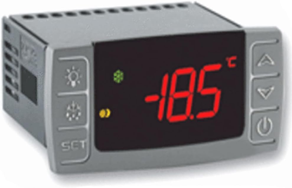
Figure 4: Close-up of the controller's display, showing a typical temperature reading during operation.
7. Maintenance
Regular maintenance helps ensure the long-term reliability and performance of your XR20CX-5N1C1 controller.
- Cleaning: Periodically clean the exterior of the controller with a soft, dry cloth. Do not use abrasive cleaners or solvents. Ensure the unit is disconnected from power before cleaning.
- Inspections: Regularly inspect all wiring connections to ensure they remain secure and free from corrosion. Check for any signs of physical damage to the controller or probes.
- Internal Access: The instrument must not be opened. There are no user-serviceable parts inside. Any internal maintenance or repair must be performed by qualified service personnel.
- Environmental Check: Ensure the operating environment remains within specified limits (temperature, humidity) to prevent condensation and other environmental damage.
Warning: Always disconnect power to the unit before performing any maintenance or inspection.
8. Troubleshooting
This section provides guidance for common issues. For complex problems or issues not listed here, contact technical support.
- Controller Not Powering On:
- Verify that the supply voltage is correct (230V/50-60Hz) and that power is reaching the unit's terminals.
- Check all power connections for looseness or damage.
- Compressor Not Starting/Stopping Correctly:
- Ensure the thermostat probe is correctly connected and functioning. A faulty probe will cause the compressor to operate based on timed parameters (COn, COF) instead of temperature.
- Check the set point and differential settings.
- Verify the compressor relay output wiring.
- Display Errors or Malfunctions:
- If the display shows unusual characters or no reading, check probe connections.
- Ensure the unit is not exposed to extreme temperatures or moisture.
- General Fault or Faulty Operation:
If the instrument exhibits any failure or faulty operation that cannot be resolved by the above steps, it is recommended to send the instrument back to the distributor. Provide a detailed description of the fault to assist with diagnosis and repair.
9. Warranty and Support
LSBYLM stands behind the quality of its products. While specific warranty terms are not detailed in this manual, please retain your proof of purchase for any warranty claims.
For technical support, troubleshooting assistance beyond what is covered in this manual, or to inquire about warranty service, please contact your authorized LSBYLM distributor or the point of purchase. When contacting support, please have your product model number (XR20CX-5N1C1) and a detailed description of the issue ready.
Manufacturer: LSBYLM