1. Introduction
This manual provides detailed instructions for the installation, operation, and maintenance of the Generic Gate Motor Controller Circuit Board, Model BFPTUAPP-6REMOTE. This control board is specifically designed for use with AC sliding gate motors, operating at either 110V or 220V AC. It features a 433.92 MHz frequency for remote control communication.
Please note that the control board may be supplied in either a green or black color. Both versions have identical functionality and specifications; the color difference is due to different production batches.

Image 1.1: Generic Gate Motor Controller Circuit Board with six remote controls.
2. Safety Information
- Electrical Safety: Installation and wiring should only be performed by qualified personnel. Ensure the main power supply is disconnected before any installation or maintenance work.
- Voltage Compatibility: This control board is designed exclusively for AC motors (110V or 220V). It is not compatible with DC motors or swing gate openers. Verify your motor type and voltage before connection.
- Remote Control Batteries: Batteries for the remote controllers are not included and must be purchased separately.
- Environmental Conditions: Protect the control board from moisture, dust, and extreme temperatures. Install it within a suitable protective enclosure.
3. Product Overview and Components
The control board features various terminals, DIP switches, and potentiometers for comprehensive control and customization of your sliding gate opener. Refer to the images below for component identification.

Image 3.1: Close-up view of the control board, showing relays, transformer, and various connectors.
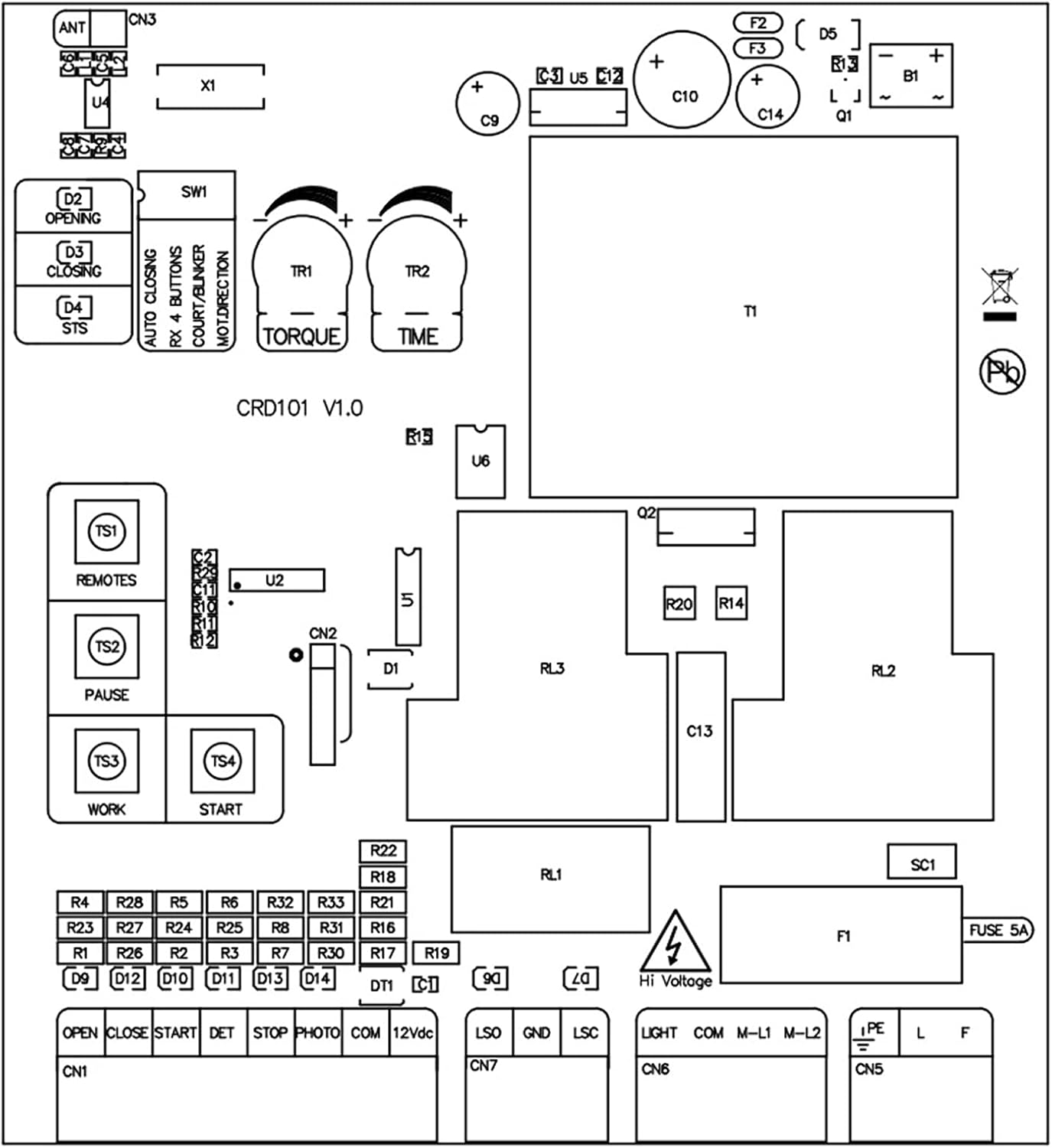
Image 3.2: Schematic diagram illustrating the layout and connections of the control board.
Key Components:
- Terminal Blocks (CN1, CN5, CN6, CN7): For connecting power, motor, limit switches, safety sensors, and external controls.
- DIP Switches (SW1): Used for configuring operational modes such as auto-closing, remote button functions, and motor direction.
- Potentiometers (TORQUE, TIME): Adjustable controls for motor force and operational timing.
- Fuse (FUSE 5A): Overcurrent protection for the circuit board.
- Antenna (ANT): For receiving signals from remote controls.
4. Setup and Installation
Before proceeding with installation, ensure all power is disconnected. Refer to Image 3.2 (Schematic Diagram) for detailed wiring connections.
Wiring Connections:
- Power Input (L, F, PE): Connect the main AC power supply (110V or 220V) to the designated terminals. Ensure proper grounding (PE).
- Motor Connections (M-L1, M-L2): Connect your AC sliding gate motor to these terminals.
- Limit Switches (OPEN, CLOSE): Connect the gate's open and close limit switches. The universal sliding gate motor does not differentiate between spring and magnet limits.
- Start Input (START): Connect an external push button or control device for initiating gate operation.
- Safety Photoelectric Sensor (PHOTO, COM, 12Vdc): Connect safety sensors (e.g., photocells) to prevent the gate from closing on an obstruction. Ensure correct polarity for 12Vdc power.
- Stop Input (STOP): Connect an emergency stop button or similar safety device.
- Common Ground (GND): Connect common ground for various accessories.
- Warning Light (LIGHT): Connect an optional warning light.

Image 4.1: Detailed view of the terminal blocks for wiring connections.
5. Operating Instructions
Remote Control Pairing:
The control board uses 433.92 MHz rolling code remote controls. To pair a new remote control:
- Press and hold the 'REMOTES' button on the control board (labeled TS1 in Image 3.2).
- While holding the 'REMOTES' button, press the desired button on your remote control.
- Release both buttons. The remote should now be paired. Repeat for additional remotes.
Basic Operation:
- Pressing the paired remote button or the 'START' button will initiate the gate's open/close cycle.
- Pressing the 'PAUSE' button (labeled TS2 in Image 3.2) will temporarily stop the gate's movement.
- The 'WORK' button (labeled TS3 in Image 3.2) and 'START' button (labeled TS4 in Image 3.2) on the board can also be used for manual operation.
6. Configuration and Settings
The control board features DIP switches and potentiometers for fine-tuning the gate's operation.
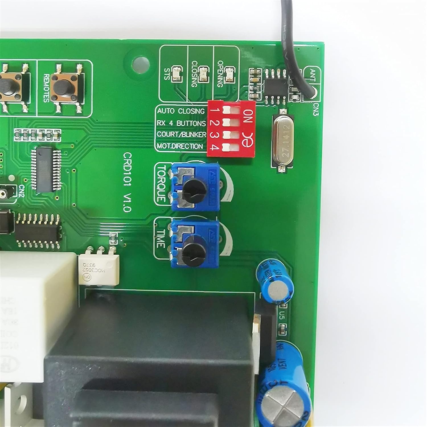
Image 6.1: Detailed view of the DIP switches (red) and potentiometers (blue) for configuration.
DIP Switches (SW1):
Adjust these switches to configure specific functions. Refer to the labels on the board next to the switches for their exact functions (e.g., AUTO CLOSING, RX 4 BUTTONS, COURT/BUNKER, MOT.DIRECTION).
- AUTO CLOSING: Enables or disables the automatic closing function after a set time.
- RX 4 BUTTONS: Configures the remote control to use 4 buttons for different functions.
- COURT/BUNKER: Specific function related to gate operation mode (consult full product documentation if available for detailed explanation).
- MOT.DIRECTION: Reverses the motor direction if the gate opens when it should close, or vice-versa.
Potentiometers:
- TORQUE: Adjusts the motor's output force. Turn clockwise to increase force, counter-clockwise to decrease. Adjust carefully to prevent excessive strain on the gate mechanism.
- TIME: Adjusts the duration for certain operations, such as the auto-closing delay or maximum motor run time. Turn clockwise to increase time, counter-clockwise to decrease.
7. Maintenance
Regular maintenance ensures the longevity and reliable operation of your gate motor controller.
- Cleaning: Periodically inspect the control board for dust, debris, or insect accumulation. Gently clean with a soft, dry brush or compressed air. Ensure power is disconnected before cleaning.
- Connection Checks: Annually check all wiring connections to ensure they are secure and free from corrosion. Loose connections can lead to intermittent operation or damage.
- Fuse Inspection: If the board loses power, check the 5A fuse. Replace it only with a fuse of the same rating (5A).
8. Troubleshooting
If you encounter issues with your gate motor controller, refer to the following common problems and solutions:
| Problem | Possible Cause | Solution |
|---|---|---|
| Gate does not respond to remote. | Remote battery dead; remote not paired; signal interference. | Replace remote battery; re-pair remote (Section 5); check for obstructions near antenna. |
| Motor does not move. | No power to board; blown fuse; loose motor connections; motor fault. | Check power supply; inspect and replace 5A fuse; verify motor wiring; consult motor manual. |
| Gate opens/closes incorrectly. | Incorrect motor direction setting; faulty limit switches. | Adjust MOT.DIRECTION DIP switch (Section 6); inspect and test limit switches. |
| Gate stops unexpectedly. | Safety sensor triggered; motor overload (torque too low); loose connections. | Check safety sensors for obstructions; increase TORQUE setting (Section 6); verify all wiring. |
9. Specifications
Technical specifications for the Generic Gate Motor Controller Circuit Board:
- Model Number: BFPTUAPP-6REMOTE
- Manufacturer: Lifyn2
- Input Voltage: 110V AC or 220V AC (for AC motors only)
- Remote Frequency: 433.92 MHz (Rolling Code)
- Material: Metal (components)
- Item Weight: Approximately 4.41 pounds
- Fuse Rating: 5A
- Date First Available: February 28, 2023

Image 9.1: Close-up view of the transformer label, indicating model and voltage specifications.
10. Warranty and Support
Specific warranty information for this product is not provided in the available details. For any technical support, warranty claims, or further inquiries, please contact the seller or manufacturer directly through your purchase platform.