Mustpoint NY-D01
Mustpoint NY-D01 DIY 40A Adjustable Spot Welding Time and Current Controller User Manual
Model: NY-D01 | Brand: Mustpoint
1. Introduction
This document provides detailed instructions for the installation, operation, and maintenance of the Mustpoint NY-D01 DIY 40A Adjustable Spot Welding Time and Current Controller. This controller is designed for DIY or simple resistance welding applications, utilizing the SCR phase shift trigger principle to adjust welding time and current for precise control.
Key Features:
- Microcontroller Control: Utilizes an STM8 industrial microcontroller as the main control core.
- Enhanced Safety: Strong and weak current paths are isolated via optocoupler for safer operation.
- Convenient Connections: Power cord and foot switch lines feature screw-free quick connect terminals for easy and reliable setup.
- Precise Input: High-precision single-bit potentiometers are used for reliable and convenient time and current input.
- Clear Status Indicators: Onboard power, status, foot switch, and trigger indicators provide clear visibility of the working state.
- Accurate Phase Shift: Designed with a reliable zero-crossing detection circuit to ensure accurate SCR phase shift.
- Thyristor Compatibility: Compatible with 40A-100A thyristors.
- Digital Interface: A digital control interface displays the current set time and current percentage.
- Adjustable Parameters: Time input range of 1-50 cycles (1 cycle = 20ms), current input range of 30-99%.
2. Safety Information
Please read and understand all safety warnings and instructions before operating this device. Failure to do so may result in electric shock, fire, serious injury, or property damage.
- Always ensure proper electrical connections and insulation.
- Do not operate the device in wet or damp conditions.
- Keep hands and other body parts away from the welding electrodes during operation.
- Wear appropriate personal protective equipment (PPE), including safety glasses and gloves.
- Ensure adequate ventilation in the work area.
- Disconnect power before performing any maintenance or adjustments.
3. Product Overview and Components
The Mustpoint NY-D01 controller consists of a main control board and a digital display module, designed for integration into a DIY spot welding setup. Key components include:
- Main Control Board: Houses the STM8 microcontroller, thyristor, and control circuitry.
- Digital Display Module: Shows welding time and current settings.
- Potentiometers: For adjusting welding time and current.
- Indicator Lights: For power, status, foot switch, and trigger.
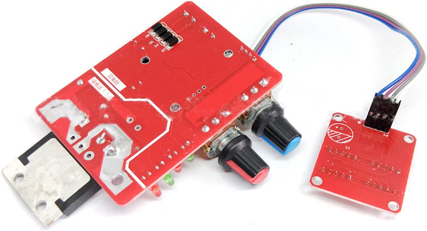
Figure 1: Top view of the Mustpoint NY-D01 Spot Welding Controller main board.
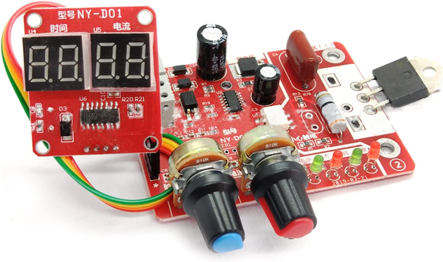
Figure 2: Angled view of the Mustpoint NY-D01 Spot Welding Controller, showing the main board and digital display module.
4. Setup and Wiring
Proper wiring is essential for the safe and effective operation of the spot welding controller. Refer to the wiring diagram below for detailed connections.
Wiring Steps:
- Connect Power: Connect the AC 220V/110V power source to the primary side of the 9V transformer.
- Connect 9V Transformer to Controller: Connect the 9V AC output from the transformer to the designated 9V AC input terminals on the control board.
- Connect Foot Switch: Connect the foot switch to the control board's foot switch terminals.
- Connect Microwave Oven Transformer: Connect the primary side of the microwave oven transformer (MOT) to the output terminals of the control board (where the thyristor is connected).
- Connect Welding Pins: Connect the welding pins (electrodes) to the secondary side of the microwave oven transformer.

Figure 3: Wiring diagram for the Mustpoint NY-D01 Spot Welding Controller, showing connections to the microwave oven transformer, 9V transformer, and foot switch.
Video: Spot Welder Control Board Overview
Video 1: This video provides a general overview of a spot welder control board, demonstrating its components and basic functionality. It can help users visualize the setup process.
5. Operating Instructions
Once the controller is correctly wired, follow these steps for operation:
- Power On: Connect the main power supply to the 9V transformer. The power indicator on the control board should illuminate.
- Adjust Welding Time: Use the high-precision potentiometer labeled for 'Time' to set the desired welding duration. The digital display will show the current time setting (1-50 cycles).
- Adjust Welding Current: Use the high-precision potentiometer labeled for 'Current' to set the desired welding current percentage. The digital display will show the current percentage (30-99%).
- Prepare for Welding: Ensure the materials to be welded are clean and properly aligned between the welding pins.
- Initiate Weld: Press the foot switch to initiate the welding process. The trigger indicator will light up during welding.
- Monitor Indicators: Observe the status indicators to ensure normal operation.
Video: UK1 Battery Spot Welder Demonstration
Video 2: This video demonstrates the practical application of a spot welder for battery assembly, showcasing the welding process and the results. While a different model, the principles of operation are similar.
6. Maintenance
Regular maintenance ensures the longevity and optimal performance of your spot welding controller.
- Keep Clean: Regularly clean the control board and terminals to prevent dust and debris accumulation.
- Check Connections: Periodically inspect all wiring connections for tightness and signs of wear or damage.
- Inspect Welding Pins: Ensure welding pins are clean and sharp for effective welding. Replace if worn or damaged.
- Storage: Store the controller in a dry, dust-free environment when not in use.
7. Troubleshooting
If you encounter issues with your Mustpoint NY-D01 controller, refer to the following common problems and solutions:
- No Power: Check the main power supply and the 9V transformer connections. Ensure the power cord is securely connected.
- Weak or Inconsistent Welds:
- Increase the welding current or time settings.
- Check the welding pins for cleanliness and sharpness.
- Ensure good contact between the welding pins and the workpiece.
- Verify the microwave oven transformer is functioning correctly.
- Overheating: Reduce welding frequency or allow the device to cool down between welds. Ensure adequate ventilation.
- Digital Display Not Working: Check the connection between the digital display module and the main control board.
8. Specifications
| Feature | Value |
|---|---|
| Package Dimensions | 5.2 x 3.19 x 1.85 inches |
| Item Weight | 0.16 ounces |
| Manufacturer | Mustpoint |
| ASIN | B0BX2RPK8R |
| Date First Available | February 28, 2023 |
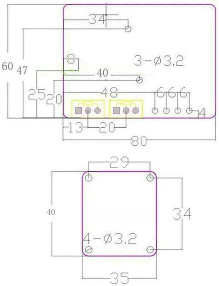
Figure 4: Technical dimensions of the Mustpoint NY-D01 Spot Welding Controller.
9. Warranty and Support
Specific warranty details and direct support contact information are not provided in the product description. For any issues or inquiries, please refer to the retailer or your point of purchase for assistance.
Related Documents - NY-D01
 |
NY-D04 100A Digital Display Spot Welding Machine Controller Manual This document provides details on the NY-D04 100A Digital Display Spot Welding Machine Transformer Controller, including its features, specifications, and usage instructions. It highlights the product's durable construction, stable performance, and ease of use for spot welding applications. |
 |
Metal Dog Cage Instruction Manual Instruction manual for the Metal Dog Cage, including assembly steps and safety warnings. Models DOGC-D01-24S, DOGC-D01-30S, DOGC-D01-36S, DOGC-D01-42S, DOGC-D01-48S. |
 |
Ulticam Dot Setup Guide - U-tec Smart Camera Installation and Configuration Comprehensive setup guide for the U-tec Ulticam Dot smart camera, detailing specifications, package contents, interface, installation methods for various surfaces, and app setup instructions. Includes FCC and IC compliance information. |
 |
Lutron Athena Wireless Node Installation Guide - Model 041838 Installation guide for the Lutron Athena Wireless Node (Model 041838), detailing component requirements, wiring, setup, and troubleshooting for lighting control systems. |
 |
Руководство по эксплуатации кондиционера воздуха FUNAI DRAGON (канальный тип) Подробное руководство пользователя для кондиционеров воздуха FUNAI серии DRAGON. Включает информацию по установке, эксплуатации, техническому обслуживанию, устранению неисправностей и технические характеристики. |
 |
Руководство по эксплуатации кондиционеров FUNAI серии DRAGON Подробное руководство по эксплуатации кондиционеров воздуха FUNAI серии DRAGON, включая установку, управление, техническое обслуживание и поиск неисправностей. |