1. Introduction
The Generic UT501A Insulation Resistance Tester is a digital megger designed for measuring insulation resistance in various electrical equipment and household appliances. This device is part of the UT500 series, capable of measuring insulation resistance, AC voltage, low resistance, Polarization Index (PI), and Dielectric Absorption Ratio (DAR). It is an essential tool for ensuring the safe and accurate operation of transformers, generators, high-voltage motors, power capacitors, power cables, arresters, and other electrical systems.
Key features include a 2000-count LCD display, an overload indicator, AC voltage measurement with backlight, automatic power-off, continuous measurement mode, a red warning light, and a buzzer function for enhanced safety and usability.
2. Safety Information
WARNING: To avoid electric shock or personal injury, please read all safety information before using this product. Use the product only as specified in this manual, or the protection provided by the product may be impaired.
- Always inspect the tester, test leads, and accessories for damage before each use. Do not use if damaged.
- Do not apply more than the rated voltage, as marked on the tester, between the terminals or between any terminal and ground.
- Use caution with voltages above 30V AC RMS, 42V peak, or 60V DC. Such voltages pose a shock hazard.
- Disconnect the test leads from the circuit under test before changing functions or ranges.
- Ensure the battery compartment is securely closed before operation.
- Do not operate the tester in explosive gas, vapor, or dusty environments.
- Always discharge the circuit under test after insulation resistance measurements. The UT501A features automatic discharge.
- Adhere to local and national safety codes.
3. Package Contents
Verify that all items listed below are present and in good condition. If any item is missing or damaged, contact your supplier.
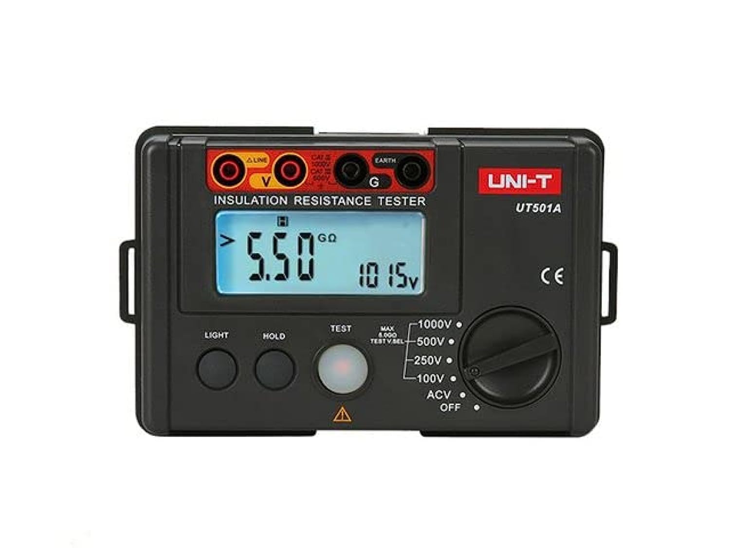
Image: The Generic UT501A Insulation Resistance Tester, including the main unit, test leads, carrying case, and user manual.
- UT501A Insulation Resistance Tester Unit
- Test Leads (Red and Black)
- Alligator Clips
- Carrying Case
- User Manual
- Shoulder Strap
4. Product Overview
The UT501A features a robust design suitable for field use. Its intuitive interface allows for easy selection of measurement functions and clear display of results.
4.1 Front Panel
- LCD Display: 2000-count display with backlight for clear readings in various lighting conditions.
- Function Rotary Switch: Used to select measurement modes (Insulation Resistance, AC Voltage, Low Resistance, etc.).
- Test Buttons: Initiate and stop measurements.
- Input Terminals: Connect test leads for various measurements.
- Overload Indicator: Visual alert for measurement range exceeding limits.
- Warning Light: Red light indicates high voltage output during insulation tests.
5. Setup
5.1 Battery Installation
The UT501A is powered by batteries (type and quantity typically specified in the full manual, assume standard AA or AAA for general instruction). To install or replace batteries:
- Ensure the tester is powered off and disconnect all test leads.
- Locate the battery compartment cover on the back of the unit.
- Unscrew or unlatch the cover and remove it.
- Insert new batteries, observing correct polarity (+ and -).
- Replace the battery compartment cover and secure it.
5.2 Connecting Test Leads
Connect the test leads to the appropriate input terminals on the tester. For insulation resistance measurements, typically the red lead connects to the 'LINE' or 'VΩ' terminal and the black lead to the 'EARTH' or 'COM' terminal. Refer to the markings on the device for specific connections for different functions.
6. Operating Instructions
Before any measurement, ensure the circuit under test is de-energized and safely isolated, unless performing AC voltage measurements.
6.1 Insulation Resistance Measurement
- Turn the rotary switch to the desired insulation resistance test voltage (e.g., 100V, 250V, 500V, 1000V).
- Connect the test leads to the circuit or component to be tested. Ensure proper contact.
- Press and hold the 'TEST' button. The red warning light will illuminate, indicating high voltage output.
- Read the insulation resistance value on the LCD display.
- Release the 'TEST' button to stop the measurement. The circuit will automatically discharge.
6.2 AC Voltage Measurement
- Turn the rotary switch to the 'ACV' position.
- Connect the test leads to the points where AC voltage is to be measured.
- The AC voltage value will be displayed on the LCD.
6.3 Low Resistance Measurement
- Turn the rotary switch to the 'Ω' (Ohms) position.
- Connect the test leads to the component or circuit for low resistance measurement.
- Read the resistance value on the LCD.
6.4 Polarization Index (PI) and Dielectric Absorption Ratio (DAR)
The UT501A can calculate PI and DAR, which are important indicators of insulation quality. These measurements typically involve taking insulation resistance readings at specific time intervals (e.g., 1 minute and 10 minutes for PI, 30 seconds and 60 seconds for DAR) and the meter automatically calculates the ratio. Refer to the detailed instructions in the full manual for specific steps on activating and interpreting these functions.
7. Maintenance
7.1 Cleaning
Wipe the case with a damp cloth and mild detergent. Do not use abrasives or solvents. Ensure the device is completely dry before use.
7.2 Storage
When not in use for extended periods, remove the batteries to prevent leakage. Store the tester and accessories in the provided carrying case in a cool, dry place, away from direct sunlight and extreme temperatures.
8. Troubleshooting
- No Display/Power: Check battery installation and charge level. Replace batteries if necessary.
- Inaccurate Readings: Ensure test leads are properly connected and not damaged. Verify the correct function and range are selected. Clean test points.
- Overload Indicator: The measured value exceeds the selected range. Select a higher range or verify the circuit conditions.
- Buzzer/Warning Light Active: This indicates high voltage output during insulation tests. This is normal during a test. If it persists after releasing the TEST button, ensure the circuit has discharged.
9. Specifications
| Feature | Specification |
|---|---|
| Brand | Generic |
| Model | UT501A |
| Power Source | Corded Electric (Note: This likely refers to the test leads, the device itself is battery-powered) |
| Color | Red |
| Measurement Type | Insulation Resistance, AC Voltage, Low Resistance, PI, DAR |
| Maximum Operating Voltage | 1000 Volts |
| Display | 2000-count LCD with backlight |
| Auto Power Off | Yes |
| Automatic Discharge | Yes |
| Country of Origin | China |
10. Warranty
This product is sold without a manufacturer's warranty. Please refer to your retailer's return policy for any issues upon purchase.
11. Support
For further assistance or inquiries regarding the Generic UT501A Insulation Resistance Tester, please contact your point of purchase or the manufacturer's customer support channels if available. Always refer to the complete user manual provided with your device for the most detailed and up-to-date information.