1. Introduction
The Teyleten Robot MCP4725 is a 12-bit Digital-to-Analog Converter (DAC) breakout module. It provides a buffered voltage output and features non-volatile memory (EEPROM) for storing configuration bits and DAC input data. This module utilizes a two-wire I2C-compatible serial interface and operates within a voltage range of 2.7V to 5.5V from a single supply. It is designed for applications requiring analog voltage output from digital microcontrollers like Arduino and Raspberry Pi.
Key Features:
- 12-bit Resolution: Provides precise analog voltage output.
- I2C Interface: Supports Standard, Fast, and High-Speed I2C communication.
- Compact Design: Small package for easy integration into projects.
- Wide Supply Voltage: Operates from 2.7V to 5.5V.
- Internal EEPROM: Stores settings for persistent configuration.
- Power-Saving Shutdown Mode: Configurable via register bits.
2. Module Overview and Pinout
The MCP4725 module features several pins for power, ground, I2C communication, and analog output. Understanding the pinout is crucial for proper connection and operation.

Figure 1: Front view of the MCP4725 module with pin labels.
This image displays the front side of the MCP4725 breakout board. Key pins visible include OUT (analog output), GND (ground), SCL (I2C clock), SDA (I2C data), VCC (power supply), and ADDR (address selection). The MCP4725 chip is centrally located on the board.
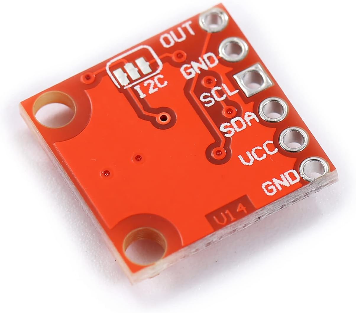
Figure 2: Back view of the MCP4725 module.
This image shows the reverse side of the MCP4725 module. It highlights additional I2C pads and repeats the VCC and GND connections, providing alternative soldering points or clearer labeling for some connections.
Pin Description:
| Pin | Description |
|---|---|
| VCC | Power supply input (2.7V to 5.5V). |
| GND | Ground connection. |
| SCL | I2C Serial Clock line. Connect to your microcontroller's SCL pin. |
| SDA | I2C Serial Data line. Connect to your microcontroller's SDA pin. |
| OUT | Analog voltage output. This is the DAC's output. |
| ADDR | I2C Address selection pin. Typically used to change the I2C address if multiple DACs are on the same bus. Refer to the MCP4725 datasheet for specific address configuration. |
3. Setup and Connection
Follow these steps to connect the MCP4725 module to your microcontroller (e.g., Arduino, Raspberry Pi).
- Power Connection: Connect the VCC pin of the MCP4725 module to the 3.3V or 5V power supply output of your microcontroller. Ensure the voltage is within the 2.7V to 5.5V operating range.
- Ground Connection: Connect the GND pin of the MCP4725 module to the Ground (GND) pin of your microcontroller.
- I2C Data Line: Connect the SDA pin of the MCP4725 module to the SDA (Serial Data) pin of your microcontroller.
- I2C Clock Line: Connect the SCL pin of the MCP4725 module to the SCL (Serial Clock) pin of your microcontroller.
- Analog Output: The OUT pin will provide the analog voltage. Connect this pin to the input of the device or circuit you wish to control with an analog signal.
- Address Pin (Optional): The ADDR pin can be used to modify the I2C address. By default, it might be pulled low or high on the breakout board. Consult the MCP4725 datasheet for details on how to change the I2C address using this pin if you need to use multiple DACs on the same bus.
Note: Most microcontrollers require external pull-up resistors on the SDA and SCL lines for I2C communication. Many breakout boards, including this one, may include these resistors. Verify your specific board's design or add 4.7kΩ pull-up resistors if necessary.
4. Operating Instructions
To operate the MCP4725, you will send digital values via the I2C interface, which the DAC will convert into a corresponding analog voltage.
Basic Operation Steps:
- Initialize I2C: In your microcontroller's code, initialize the I2C communication bus.
- Set DAC Value: Use the I2C interface to send a 12-bit digital value to the MCP4725. This value will determine the output voltage. The output voltage is typically calculated as
(Digital Value / 4095) * VCC, where 4095 is the maximum 12-bit value (2^12 - 1). - Power Modes: The MCP4725 supports normal operation and a power-saving shutdown mode. You can configure these modes by writing to the device's configuration registers via I2C. Refer to the MCP4725 datasheet for detailed register maps and commands.
- EEPROM Storage: The module includes internal EEPROM. You can store the DAC input data and configuration bits in this non-volatile memory. This allows the DAC to retain its last state even after power cycling.
Example (Conceptual - Arduino):
While specific code depends on your library and setup, the general idea involves:
#include <Wire.h> // For I2C communication

#define MCP4725_ADDRESS 0x60 // Default I2C address

void setup() {
  Wire.begin(); // Initialize I2C
  Serial.begin(9600);
}

void loop() {
  for (int i = 0; i < 4096; i++) { // Cycle through 0 to 4095
    setVoltage(i);
    delay(1); // Small delay
  }
}

void setVoltage(int value) {
  Wire.beginTransmission(MCP4725_ADDRESS);
  Wire.write(0x40); // Command to write DAC input register (without EEPROM write)
  Wire.write(value >> 4); // Upper 8 bits
  Wire.write(value & 0xFF); // Lower 4 bits (shifted left by 4 in the chip)
  Wire.endTransmission();
}
Note: This is a simplified example. For robust applications, consider using a dedicated MCP4725 library for your platform (e.g., Adafruit MCP4725 library for Arduino) which handles the I2C commands and data formatting.
5. Maintenance
The MCP4725 module is a robust electronic component that requires minimal maintenance.
- Handling: Always handle the module by its edges to avoid touching the electronic components, which can be sensitive to static discharge.
- Cleaning: If necessary, gently clean the board with a soft, dry brush or compressed air to remove dust. Avoid using liquids or abrasive materials.
- Storage: Store the module in an anti-static bag in a dry environment when not in use.
- Power Supply: Ensure your power supply is stable and within the specified voltage range (2.7V to 5.5V) to prevent damage.
6. Troubleshooting
If you encounter issues with your MCP4725 module, consider the following troubleshooting steps:
- No Output Voltage / Incorrect Voltage:
- Verify all power (VCC, GND) and I2C (SDA, SCL) connections are secure and correct.
- Check your microcontroller's code for correct I2C initialization and data transmission.
- Ensure the I2C address used in your code matches the module's address (default is often 0x60 or 0x62).
- Confirm that the input voltage (VCC) is stable and within the 2.7V to 5.5V range.
- Check for external pull-up resistors on SDA/SCL if your microcontroller or breakout board does not provide them.
- I2C Communication Errors:
- Double-check wiring for SDA and SCL.
- Use an I2C scanner sketch (available for Arduino) to confirm the module is detected on the bus and its address.
- Ensure the I2C bus speed is compatible with both the microcontroller and the MCP4725.
- Module Not Responding:
- Power cycle the entire setup.
- Inspect the module for any visible damage or solder bridges.
- Test with a different microcontroller or a known working I2C device to isolate the problem.
7. Specifications
| Feature | Detail |
|---|---|
| Model Name | MCP4725 |
| Brand | Teyleten Robot |
| Resolution | 12-bit |
| Interface | I2C (Standard, Fast, High-Speed compatible) |
| Supply Voltage | 2.7V to 5.5V |
| Internal Memory | EEPROM for settings and DAC input data |
| Compatible Devices | Arduino, Raspberry Pi, and other microcontrollers with I2C |
| Operating System Compatibility | Linux (for Raspberry Pi), Arduino IDE environments |
8. Warranty and Support
This product is typically covered by a standard manufacturer's warranty against defects in materials and workmanship. For specific warranty details, return policies, or technical support, please refer to the retailer's policy where the product was purchased or contact Teyleten Robot customer service directly.
For additional resources, datasheets, and community support, search online for "MCP4725 datasheet" or "Arduino MCP4725 tutorial".