1. Introduction
The SIRS-E DMX-CON4-C2 is a 4-channel DMX512 LED decoder designed to control LED strips and modules. It converts standard DMX512 digital signals into PWM signals, allowing for precise brightness control of connected LED lighting. This decoder supports 1-4 color LED lights and offers 256 levels of brightness per channel, ensuring smooth dimming and color mixing. Its 5.2 kHz flicker-free frequency makes it suitable for video applications.
2. Product Features
- Meets DMX512/1990 standard.
- Provides 256 levels of brightness control for full-color effects.
- Features 4 output channels with a maximum total output of 100W.
- Capable of achieving asynchronous color change effects.
- Supports control of LED lights with 1 to 4 colors (RGBW, RGB, White, Single Color).
- Allows free setting of DMX address from 1-512.
- Modular design compatible with various LED modules.
- Class 2 circuit with isolated DMX input.
- UL Listed (UL2108, E479339) for safety and reliability.
- Flicker-free operation at 5.2 kHz, ideal for video recording environments.
- Input voltage: 12-24V DC.

Image: SIRS-E DMX-CON4-C2 LED Decoder highlighting its features and UL listing.
3. Safety Information
Please read and understand all instructions before installation and operation. Failure to follow these instructions may result in electric shock, fire, or serious injury.
- Ensure the power supply is disconnected before any installation or wiring.
- This device is designed for 12-24V DC input only. Do not connect to AC power or voltages outside this range.
- Ensure proper polarity when connecting power and LED outputs. Incorrect wiring can damage the device and connected LEDs.
- Do not exceed the maximum output wattage of 100W. Overloading can lead to overheating and damage.
- Install in a well-ventilated area, away from direct sunlight, high temperatures, and moisture.
- This device is UL Listed for Dry or Damp Locations. Do not expose to water or extreme humidity.
- All wiring should be performed by a qualified electrician in accordance with local electrical codes.
4. Package Contents
Verify that all items are present in the package:
- 1x SIRS-E DMX-CON4-C2 LED Decoder
- 1x Datasheet
5. Physical Layout and Dimensions
Familiarize yourself with the components and dimensions of the DMX-CON4-C2 decoder.

Image: Top view of the DMX-CON4-C2 decoder, indicating DMX input/output, DIP switches for addressing, and LED output terminals.

Image: Front view of the DMX-CON4-C2 decoder, highlighting the RJ45 DMX In/Out ports.

Image: Rear view of the DMX-CON4-C2 decoder, showing the green terminal block for power input and LED output connections.

Diagram: Physical layout of the DMX-CON4-C2, detailing the RJ45 isolated DMX In/Out, DMX DIP switch address selector, and output channels with common V+ and DC 12V input.
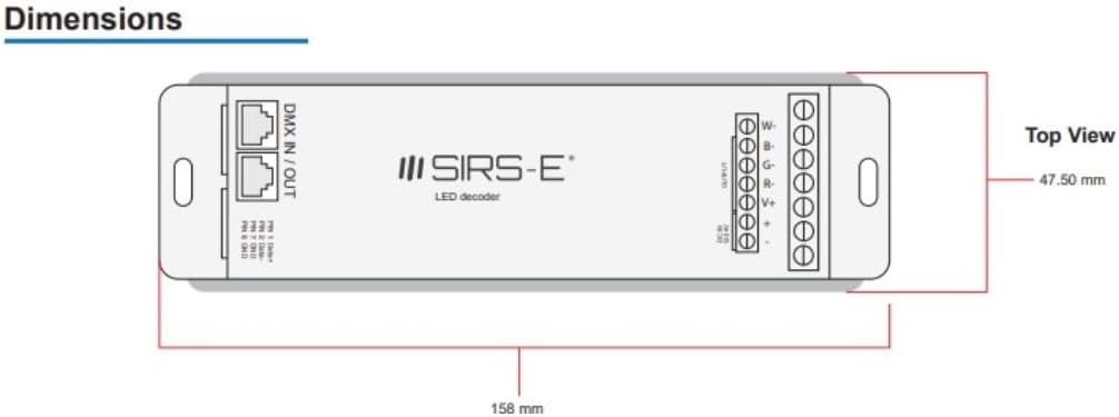
Diagram: Top view dimensions of the DMX-CON4-C2, showing a length of 158 mm and a width of 47.50 mm.

Diagram: Side view dimensions of the DMX-CON4-C2, showing a height of 22.35 mm.
6. Setup and Installation
6.1 Wiring Connections
Before making any connections, ensure the power supply is OFF.
- Power Input: Connect your 12-24V DC power supply to the "DC IN 12-24V" terminals on the green terminal block. Ensure correct polarity: connect the positive (+) wire to the '+' terminal and the negative (-) wire to the '-' terminal.
- LED Output: Connect your LED strips or modules to the "OUTPUT" terminals. The DMX-CON4-C2 has four output channels (R, G, B, W or 1, 2, 3, 4) and a common positive (V+).
- For RGBW LED strips: Connect the Red wire to 'R', Green to 'G', Blue to 'B', White to 'W', and the common positive to 'V+'.
- For RGB LED strips: Connect Red to 'R', Green to 'G', Blue to 'B', and the common positive to 'V+'. The 'W' terminal can be left unused.
- For single color LED strips: Connect the negative wire to any of the 'R', 'G', 'B', or 'W' terminals and the positive wire to 'V+'.
- DMX Input/Output: Connect your DMX controller to the "DMX IN" RJ45 port. If daisy-chaining multiple decoders, connect the "DMX OUT" RJ45 port of the first decoder to the "DMX IN" of the next.
- Pin 1: Data+
- Pin 2: Data-
- Pin 7: GND
- Pin 8: GND
6.2 DMX Address Setting (DIP Switches)
The DMX-CON4-C2 uses 10 DIP switches to set its DMX starting address. Each switch corresponds to a binary value, which sums up to the DMX address. Switch 1 is the least significant bit (1), and Switch 9 is the most significant bit (256). Switch 10 is typically reserved or used for special functions (e.g., test mode, master/slave, or specific dimming curves) and should generally be OFF unless specified otherwise in advanced documentation.
To set the DMX address:
- OFF position = 0 (switch is down)
- ON position = 1 (switch is up)
The DMX starting address is the sum of the values of the ON switches (1-9). For example:
- Address 1: Switch 1 ON, others OFF.
- Address 2: Switch 2 ON, others OFF.
- Address 3: Switch 1 ON, Switch 2 ON, others OFF (1+2=3).
- Address 256: Switch 9 ON, others OFF.
Since the decoder uses 4 channels (RGBW), if its starting address is N, it will occupy DMX channels N, N+1, N+2, and N+3.
7. Operating Instructions
Once the DMX-CON4-C2 decoder is correctly wired and its DMX address is set, it is ready to receive commands from a DMX512 controller.
- Power On: Apply 12-24V DC power to the decoder. The status indicator (if present) should illuminate.
- DMX Controller Setup: Configure your DMX controller to send signals to the DMX address you set on the decoder. Ensure the controller is set to output DMX512 protocol.
- Channel Control:
- The first DMX channel (your set address) controls the Red (or Channel 1) output.
- The second DMX channel (address + 1) controls the Green (or Channel 2) output.
- The third DMX channel (address + 2) controls the Blue (or Channel 3) output.
- The fourth DMX channel (address + 3) controls the White (or Channel 4) output.
- Flicker-Free Operation: The 5.2 kHz PWM frequency ensures smooth dimming and eliminates flickering, making it suitable for video recording and broadcast environments.
8. Maintenance
The SIRS-E DMX-CON4-C2 LED Decoder requires minimal maintenance.
- Cleaning: Periodically clean the exterior of the device with a soft, dry cloth. Do not use abrasive cleaners or solvents.
- Environment: Ensure the operating environment remains within specified temperature and humidity ranges. Avoid excessive dust, moisture, and direct heat sources.
- Connections: Periodically check all wiring connections to ensure they are secure and free from corrosion.
9. Troubleshooting
| Problem | Possible Cause | Solution |
|---|---|---|
| LEDs do not light up. | No power to decoder; incorrect power wiring; DMX signal issue; incorrect DMX address; faulty LEDs. | Check power supply connection and voltage. Verify power supply is active. Check LED wiring polarity. Ensure DMX controller is sending signal. Verify DMX address on decoder matches controller. Test LEDs with a known working power source. |
| LEDs flicker or behave erratically. | Poor DMX signal; DMX termination issue; power supply instability; DMX address conflict. | Ensure DMX cables are secure and of good quality. Use a DMX terminator at the end of the DMX chain. Check power supply for stable output. Verify no other DMX devices are using the same address range. |
| Only some LED channels respond. | Incorrect LED wiring; DMX controller channel mapping issue. | Check wiring for the non-responsive channels. Verify DMX controller's channel mapping for RGBW outputs. |
| Device feels hot. | Overloaded output; insufficient ventilation. | Reduce the load on the output channels (ensure total wattage is below 100W). Ensure adequate airflow around the device. |
10. Specifications
| Attribute | Value |
|---|---|
| Model Number | DMX-CON4-C2 |
| Input Voltage | 12-24V DC |
| Output Channels | 4 Channels (RGBW) |
| Max Output Wattage | 100 Watts |
| DMX Standard | DMX512/1990 |
| Brightness Levels | 256 levels per channel |
| PWM Frequency | 5.2 kHz (Flicker Free) |
| Certifications | UL Listed (UL2108, E479339), Class 2 |
| Dimensions (L x W x H) | 6.2 x 1.8 x 0.9 inches (158 x 47.5 x 22.35 mm) |
| Item Weight | 6.2 ounces |
| Color | Black |
| Operating Environment | Dry or Damp Locations |
11. Warranty and Support
SIRS-E products are designed for reliability and performance. For specific warranty details, please refer to the warranty card included with your product or visit the official SIRS-E website. Keep your purchase receipt as proof of purchase for warranty claims.
For technical support, troubleshooting assistance, or inquiries about replacement parts, please contact SIRS-E customer service through their official website or the contact information provided in your product documentation. When contacting support, please have your product model number (DMX-CON4-C2) and purchase date ready.
SIRS-E Official Website: www.sirs-e.com


