Introduction
This manual provides comprehensive instructions for the safe and effective use of the VEVOR BS-1 Dividing Head. It covers product overview, specifications, setup, operation, maintenance, and troubleshooting. Please read this manual thoroughly before operating the device to ensure proper function and longevity.
Product Overview
The VEVOR BS-1 Dividing Head is a precision tool designed for various machining operations such as milling, grinding, and drilling. It allows for accurate division of workpieces into precise angles or divisions.

Figure 1: Complete VEVOR BS-1 Dividing Head Set. This image displays the main dividing head unit, the 3-jaw chuck, the tailstock, and various included accessories such as dividing plates, wrenches, and chuck jaws. The robust construction is evident, highlighting the primary components of the system.
Key Features
- Adjustable Angle: The dividing head can be tilted from 0° to 90° for versatile machining operations.
- Rugged Construction: Made from high-quality alloy steel, ensuring durability and precision.
- Quick-Dividing Design: Features a direct indexing mechanism for rapid and accurate divisions.
- MT3 Tailstock: Provides stable support for longer workpieces during machining.
- Universal Dividing Plates: Includes three interchangeable dividing plates for a wide range of divisions.
- Wide Application: Compatible with various milling, grinding, and drilling machines.

Figure 2: Adjustable Angle 0°-90°. This illustration demonstrates the range of angular adjustment for the dividing head, showing positions at 0°, 45°, and 90° relative to the base, allowing for diverse machining setups.

Figure 3: Ruggedly Constructed Dividing Head. A close-up view highlighting the robust build quality and material strength of the dividing head, indicating its suitability for heavy-duty use.

Figure 4: Quick-Dividing Design. This image focuses on the indexing plate and pointer, illustrating the mechanism for quick and precise angular divisions, essential for repetitive machining tasks.

Figure 5: MT3 Tailstock. A detailed view of the tailstock, showing its dimensions and the MT3 taper, which is crucial for supporting workpieces and ensuring stability during operations.

Figure 6: Universal 3 Plates. This image displays the three included dividing plates, each with different hole patterns, enabling a broad spectrum of division possibilities for various machining requirements.

Figure 7: Wide Application. This composite image illustrates the versatility of the dividing head by showing it in conjunction with different types of milling and drilling machines, demonstrating its broad compatibility.
Included Components
- Dividing Head Unit
- 6" 3-jaw Chuck
- Tailstock (MT3)
- Dividing Plates (3 pcs)
- Chuck Jaws
- Dead Center
- Wrenches and Fasteners
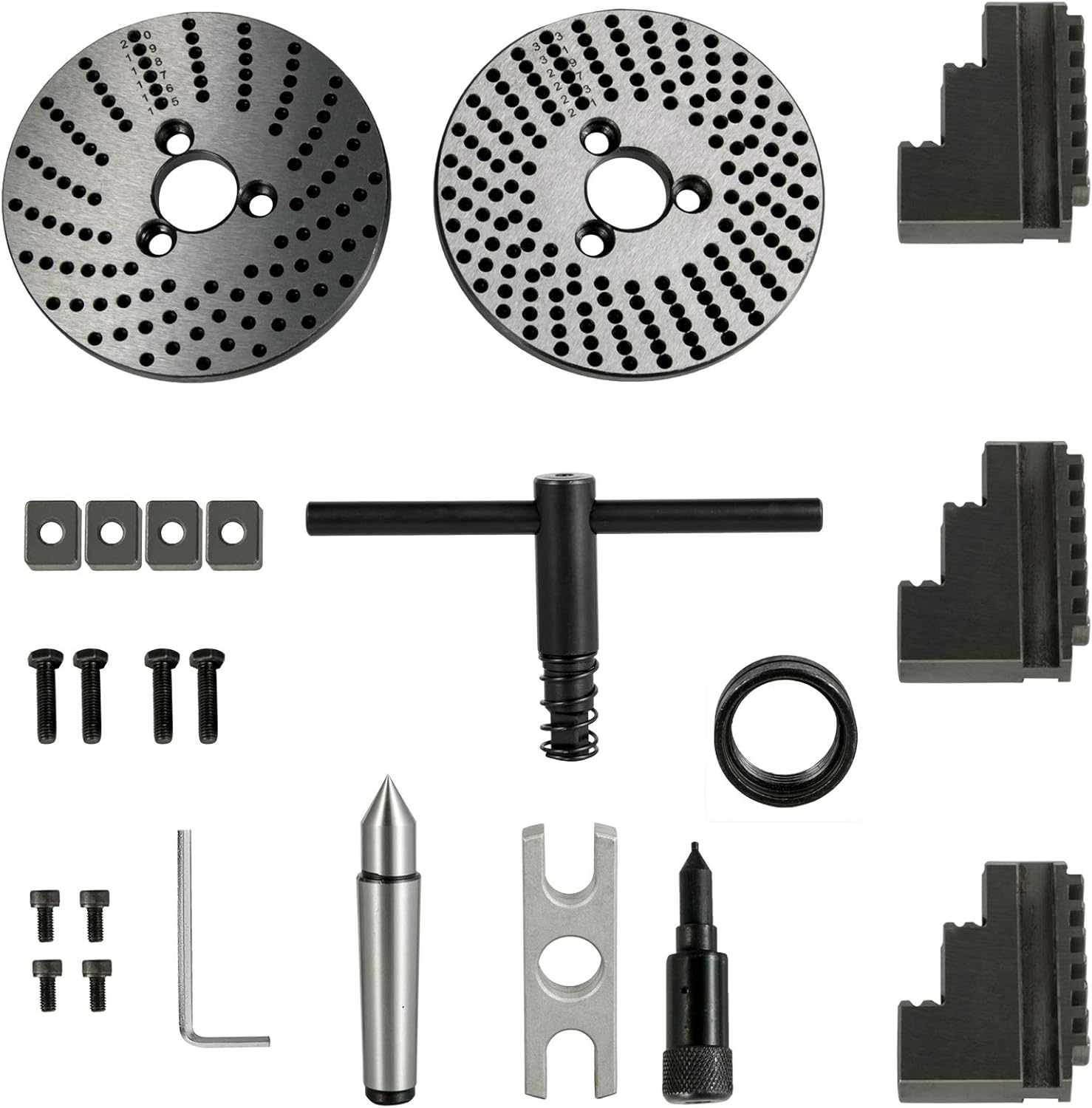
Figure 8: All Included Components. A comprehensive view of every item included in the VEVOR BS-1 Dividing Head set, providing a clear inventory for users to verify their package contents.
Specifications
| Attribute | Value |
|---|---|
| Brand | VEVOR |
| Model | BS-1 |
| Material | Alloy Steel |
| Chuck Size | 6 inches (3-jaw) |
| Tailstock Taper | MT3 |
| Dividing Plates | 3 Universal Plates Included |
| Compatible Devices | Lathe, Milling Machine, Grinding Machine, Drilling Machine |
| Package Dimensions | 20.9 x 11.4 x 11 inches |
| UPC | 840349922201 |
| ASIN | B0BWMSSYS8 |

Figure 9: Product Dimensions. This image provides key measurements for both the dividing head and the tailstock, including height, width, and length, which are essential for installation and compatibility checks.
Setup and Installation
- Unpacking: Carefully remove all components from the packaging. Inspect for any shipping damage. Retain packaging for future transport or storage.
- Cleaning: Clean all protective coatings and grease from the dividing head and accessories using a suitable degreaser.
- Mounting the Dividing Head:
- Position the dividing head on the machine table (e.g., milling machine table).
- Secure the dividing head using appropriate T-nuts and bolts through the base mounting holes. Ensure it is firmly clamped to prevent movement during operation.
- Verify the alignment of the dividing head with the machine's spindle axis.
- Attaching the Chuck:
- Mount the 6-inch 3-jaw chuck onto the spindle of the dividing head. Ensure it is seated correctly and tighten the mounting bolts securely.
- Insert the chuck jaws into the chuck body and ensure they operate smoothly.
- Installing the Tailstock:
- Place the MT3 tailstock on the machine table, aligning its center height with the dividing head's spindle center.
- Secure the tailstock to the machine table using T-nuts and bolts.
- Insert the dead center into the tailstock spindle.
- Selecting Dividing Plates: Choose the appropriate dividing plate based on the desired number of divisions. Install the selected plate onto the dividing head.
- Lubrication: Apply a thin layer of machine oil to all moving parts and precision surfaces to ensure smooth operation and prevent corrosion.
Operation
General Operation Principles
The VEVOR BS-1 Dividing Head allows for precise angular indexing of workpieces. The primary methods of operation include direct indexing and indirect indexing using the worm and worm wheel mechanism with dividing plates.
Direct Indexing
Direct indexing is used for quick divisions into a small number of equal parts (e.g., 2, 3, 4, 6, 8, 12, 24). This method utilizes the direct indexing plate usually located at the front of the spindle.
- Disengage the worm gear from the worm wheel by pulling out the indexing pin.
- Rotate the spindle by hand to the desired division, aligning the indexing pin with the corresponding hole on the direct indexing plate.
- Engage the indexing pin to lock the spindle in position.
- Perform the machining operation.
Indirect Indexing (Differential Indexing)
Indirect indexing is used for a wider range of divisions that cannot be achieved by direct indexing. This method involves calculating the number of turns of the indexing crank and the specific hole circle on the dividing plate.
- Calculate Indexing: The standard ratio for the worm and worm wheel is 40:1 (40 turns of the crank for one full revolution of the spindle). The formula for calculating the turns of the crank is: Turns = 40 / N, where N is the desired number of divisions.
- Select Dividing Plate: Choose a dividing plate with a hole circle that allows for the calculated fractional turn. For example, if you need 1/2 turn, select a plate with an even number of holes and move half the number of holes.
- Set Sector Arms: Adjust the sector arms to span the required number of holes for the fractional part of the turn.
- Engage Worm Gear: Ensure the worm gear is engaged with the worm wheel.
- Perform Indexing: Rotate the indexing crank the calculated number of full turns and then move the sector arms to the next position for the fractional part.
- Lock Position: Ensure the indexing pin is securely engaged in the correct hole.
- Machining: Proceed with the machining operation.
Adjusting the Angle of the Dividing Head
The dividing head can be tilted to machine angled surfaces or features.
- Loosen the locking bolts on the side of the dividing head base.
- Carefully tilt the head to the desired angle, using the angle scale for precision.
- Once the desired angle is set, securely tighten the locking bolts to prevent movement during operation.
Maintenance
Regular maintenance is crucial for the longevity and accuracy of your VEVOR BS-1 Dividing Head.
- Cleaning: After each use, clean the dividing head thoroughly to remove chips, dust, and coolant residue. Use a brush or compressed air.
- Lubrication: Regularly lubricate all moving parts, including the worm gear, spindle bearings, and sliding surfaces, with high-quality machine oil.
- Inspection: Periodically inspect all bolts, nuts, and fasteners for tightness. Tighten any loose components.
- Storage: When not in use, store the dividing head in a clean, dry environment to prevent rust and corrosion. Apply a thin layer of rust preventative oil to all exposed metal surfaces.
- Chuck Maintenance: Keep the chuck jaws clean and lubricated. Inspect for wear or damage.
- Tailstock Maintenance: Ensure the tailstock spindle moves smoothly. Keep the dead center clean and free of burrs.
Troubleshooting
| Problem | Possible Cause | Solution |
|---|---|---|
| Inaccurate Divisions | Loose mounting bolts; Incorrect indexing calculation; Worn worm gear/worm wheel; Dirty indexing plate holes. | Tighten all mounting bolts. Recheck indexing calculations. Inspect and replace worn parts if necessary. Clean indexing plate holes and indexing pin. |
| Stiff Operation / Difficulty Rotating Crank | Lack of lubrication; Accumulation of chips/debris; Over-tightened components. | Apply machine oil to all moving parts. Clean thoroughly to remove debris. Loosen any over-tightened bolts, then re-tighten to proper torque. |
| Chuck Jaws Not Moving Smoothly | Dirt or chips in jaw slides; Insufficient lubrication; Damaged jaws. | Remove jaws and clean jaw slides thoroughly. Lubricate jaw slides. Replace damaged jaws. |
| Tailstock Not Holding Workpiece Firmly | Loose tailstock clamping; Worn dead center; Improper alignment. | Ensure tailstock is securely clamped to the machine table. Inspect and replace worn dead center. Re-align tailstock with dividing head spindle. |
| Rust or Corrosion Appears | Improper storage; Lack of protective oil. | Clean affected areas and apply rust preventative oil. Store in a dry environment. |
Warranty and Support
For warranty information, technical support, or to inquire about replacement parts, please contact VEVOR customer service. Keep your purchase receipt and product model number (BS-1) readily available when contacting support.
You can typically find contact information on the official VEVOR website or through your original point of purchase.
Note: Specific warranty terms may vary by region and retailer.