1. Product Overview
The Lemon RX LM0086VP is a generation 2 DSMP 7-channel full-range telemetry stabilizer receiver. It offers compatibility with DSMX and DSM2 systems, providing advanced features for responsive control in both electric and gasoline engine applications.
Key Features:
- Technology: DSMP with GEN2 SDR stack (DSMX / DSM2 compatibility).
- Channels: 7-channel full-range telemetry stabilizer.
- Telemetry: Integrated Barometer, Altimeter, Energy meter (requires V/I sensor), and Internal Temperature Sensor.
- Stabilization: High sensitivity gyro with proprietary algorithm for responsive control.
- Power: BEC1 and BEC2 dual inputs for high-reliability operation and high current drain servos.
- Mixers: Built-in Delta, V-tail, and Normal Wing mixers.
- Aileron Support: Supports stabilization with separated channel dual aileron operation.
- Stabilization Control: Always-on feature with real-time variable stabilization gain control on channel 8.
- Failsafe: All-channel failsafe.
- Signal Reliability: Antenna diversity and satellite port for additional signal diversity.
- Gyro Activation: Via AUX2 or Gear channel.
- Gain Tuning: 3 potentiometers for individual gain tuning.
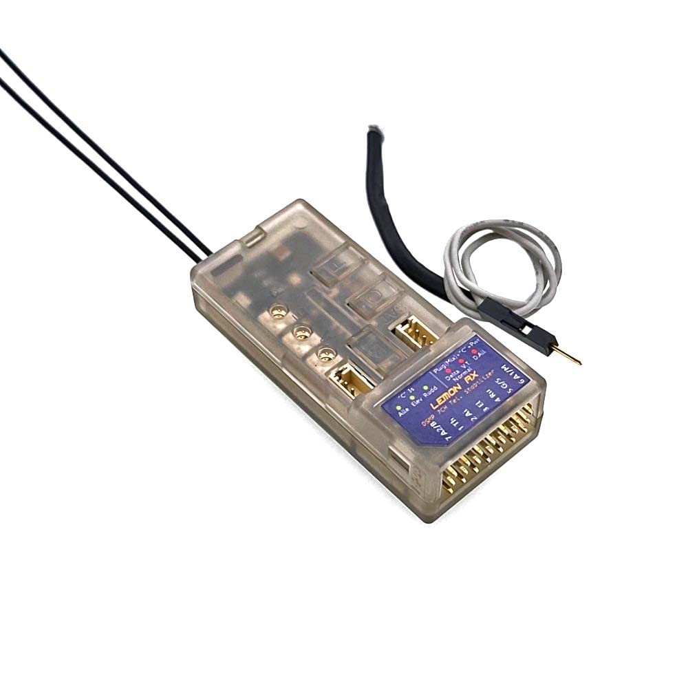
Figure 1: Lemon RX LM0086VP DSMP 7-Channel Receiver with connected wires.
2. Setup and Binding
2.1. Basic Binding Procedure
- Ensure your transmitter is set to the correct protocol (DSMP, DSMX, or DSM2).
- Insert the bind plug into Channel 6 on the receiver.
- Power on the receiver. The LEDs on the receiver will flash, indicating it is in bind mode.
- Initiate the binding process on your transmitter.
- Once bound, the receiver LEDs will stop flashing and remain solid.
- Remove the bind plug from the receiver.
Video 1: Demonstrates how to set up the receiver with a Radiomaster TX16S transmitter, including the binding process.
2.2. Failsafe Setup
The default failsafe setting is 'no pulses'. To customize failsafe positions:
- With the receiver bound and powered on, position your transmitter sticks and switches to the desired failsafe positions (e.g., mid-throttle, slight elevator up).
- Press and hold the 'F' button on the receiver for approximately 3 seconds until the blue light illuminates.
- Release the 'F' button. The failsafe positions are now set.
- To revert to 'no pulses' failsafe, press and hold the 'F' button again until the blue light turns off.
2.3. Stabilization Type Setup
To configure the stabilization for your aircraft type (e.g., conventional tail, Delta, V-tail):
- Insert the bind plug into Channel 6.
- Press and hold the 'C' button on the receiver while powering it on.
- All six programming LEDs (three red, three blue) will flash.
- Press the 'C' button repeatedly to cycle through the different tail types. The illuminated LEDs (e.g., R1 and R2 for conventional tail) will indicate the selected type.
- Once your preferred tail type is indicated by the LEDs, press the 'C' button twice quickly to save the setting. The lights will then remain solid.
Video 2: Explains how to activate stabilization and set the aircraft tail type on the receiver.
2.4. Master Gain Control Setup
To assign a switch or dial on your transmitter for real-time variable stabilization gain control (Channel 8):
- With the receiver bound and powered on, insert the bind plug into Channel 5.
- Press and hold the 'C' button on the receiver while powering it on.
- All six programming LEDs will flash.
- The LEDs will indicate the assigned channel for master gain (e.g., green for Channel 7, blue for Channel 5). Press 'C' to cycle if needed.
- On your transmitter, go to the 'Mixes' menu.
- Add a new mix for Channel 8.
- Set the source for this mix to your desired switch or dial (e.g., S1 dial for variable control).
- The receiver's green status light will indicate that stabilization is active and controllable via the assigned channel.
2.5. Telemetry Setup (Voltage Probe)
To enable full-range telemetry, including battery voltage monitoring:
- Connect the voltage probe to the designated port on the receiver (labeled 'Voltage Probe' or similar).
- Connect the other end of the voltage probe to the positive lead of your aircraft's battery balance cable.
- Power on the receiver and transmitter.
- After approximately 60 seconds, the transmitter should display telemetry data, including battery voltage.
Video 3: Details the setup process for telemetry, including connecting the voltage probe and monitoring data on the transmitter.
3. Operating the Receiver
3.1. Stabilization Activation
Once configured, the stabilization feature can be activated or deactivated during flight using the assigned switch on your transmitter (e.g., Channel 7 or AUX2/Gear channel). When stabilization is active, the receiver's green status light will be on.
3.2. Adjusting Master Gain
The master gain for stabilization can be adjusted in real-time using the assigned dial or switch on your transmitter (Channel 8). This allows for fine-tuning the level of stabilization to suit flying conditions and personal preference.
3.3. Monitoring Telemetry
Telemetry data, including battery voltage, altitude, and internal temperature, can be monitored directly on your compatible transmitter's display. This provides critical real-time information about your aircraft's status during flight.
4. Maintenance
4.1. Factory Reset
If you need to use the receiver in a new aircraft or wish to clear all previous settings, you can perform a factory reset:
- Ensure the receiver is powered off.
- Press and hold both the 'B' and 'F' buttons simultaneously.
- While holding the buttons, power on the receiver.
- Continue holding the buttons until all LEDs on the receiver illuminate.
- Release the buttons. The receiver has now been factory reset to its default settings.
4.2. General Care
- Keep the receiver dry and away from moisture.
- Avoid exposing the receiver to extreme temperatures.
- Regularly check all connections for secure fit and signs of wear.
5. Troubleshooting
- Receiver not binding: Ensure the transmitter is set to the correct protocol (DSMP, DSMX, or DSM2) and the bind plug is correctly inserted. Try rebinding.
- No telemetry data: Verify the voltage probe is correctly connected to both the receiver and the battery balance cable. Check transmitter settings for telemetry display.
- Stabilization not active: Confirm the stabilization channel (e.g., Channel 7) is correctly assigned and activated on your transmitter. Check the receiver's green status light.
- Incorrect control response: Perform a factory reset and reconfigure all settings, paying close attention to tail type and channel assignments.
6. Technical Specifications
| Feature | Specification |
|---|---|
| Dimension | 55mm x 15mm x 23mm |
| Recommended Voltage Range | 3.9V to 8.5V (2S LiPo capable) |
| Technology | DSMP with GEN2 SDR stack (DSMX / DSM2 compatibility) |
| Channels | 7-channel |
| Telemetry Options | Barometer, Altimeter, Energy meter (requires V/I sensor), Internal Temperature Sensor |
| Gyro Sensitivity | High sensitivity |
| BEC Inputs | Dual (BEC1 and BEC2) |
| Wing Mixers | Built-in Delta, V-tail, Normal Wing |
| Stabilization Gain Control | Real-time variable on Channel 8 |
| Failsafe | All-channel |
| Antenna | Diversity with Satellite port |
| Gain Tuning | 3 potentiometers |
| Manufacturer | Lemon-RX |
| Material Type | Aluminum, Plastic |
| Operation Mode | Automatic |
7. Warranty and Support
For detailed warranty information and additional support resources, please refer to the official Lemon RX website. This manual provides operational guidance; specific warranty terms are subject to the manufacturer's policy.
For further assistance, please visit: www.lemon-rx.com/manual