1. Introduction
The LianGSanSan H803TV is an online master controller designed for LED display systems. It transmits data via DVI/HDMI interfaces, offering high-speed data transfer and extensive control capabilities. This controller operates independently of specific software, allowing direct connection to various computers and DVI/HDMI-compatible devices. It supports dual-monitor, multi-monitor extension, and duplication modes, with duplication mode being the primary setup when connected to a computer.
For advanced control, the H803TV can be used with auxiliary slave controllers such as H801RA and H801RC. The recommended auxiliary software is "LED Studio Software".
2. Package Contents
Verify that all items listed below are included in your package:
- H803TV LED DVI Controller
- DVI Cable
- USB Cable
- DC 9V Power Supply

Image: The H803TV LED DVI Controller shown with its accompanying DVI cable, USB cable, and DC 9V power supply.
3. Performance and Specifications
3.1 Performance Overview
- Each H803TV unit supports a maximum of 400,000 pixels.
- Equipped with four output network ports, each port can control a maximum of 100,000 pixels.
- The four ports operate separately and are configured individually, allowing them to drive different types of chips.
- Four ports can control up to 1020 slave controllers in total, with each port managing a maximum of 255 slave controllers.
- Supports connecting a video splitter to control parts of the video section by section.
- Supported resolutions include: 1024x768, 1280x720, 1280x960, 1280x1024, 1360x765, 1360x1020, 1600x900, 1600x1200.
- Screen refresh frequency is recommended to be set to 60Hz.
- Supports single channel and double channel lamps.
- The autorun USB feature is used to transmit and control data, compatible with both 32-bit and 64-bit operating systems.
- Data transmission is based on standard Ethernet protocol, with a transmission distance of up to 100 meters.
3.2 Technical Specifications
| Parameter | Value |
|---|---|
| Input Voltage | DC 9V |
| Power Consumption | 5W |
| Control Pixels | 400,000 pixels (one computer controls 3.84 million pixels) |
| Weight | 0.8 kg |
| Working Temperature | -20°C to 75°C |
| Dimension (L x W x H) | 183mm x 139mm x 40mm |
| Carton Dimension (L x W x H) | 205mm x 168mm x 69mm |
4. Supported Chips
The H803TV controller supports a wide range of LED driver chips, including but not limited to:
LPD6803, LPD8806, LPD1882, LPD1889, LPD6812, LPD1883, LPD1886, DMX512, HDMX, APA102, MY9221, DZ2809, SM16716, SM16711, UCS6909, UCS6912, UCS1903, UCS1909, UCS1912, WS2801, WS2803, WS2811, INK1003, TM1812, TM1809, TM1804, TM1803, TM1913, TM1914, TM1926, TM1829, TM1906, TM1814, BS0901, BS0902, BS0825, BS0815, LY6620, LD1510, LD1512, LD1530, LD1532, TLS3001, TLS3002, DM412, DM413, DM114, DM115, DM13C, DM134, DM135, DM136, MBI6023, MBI6024, MBI5001, MBI5168, MBI5016, MBI5026, MBI5027, 74HC595, 6B595, TB62726, TB62706, ST2221A, ST2221C.
5. Setup and Connection
5.1 Basic Connection Diagram
The H803TV controller connects to a computer via USB and DVI/HDMI, and then distributes data to slave controllers via network cables. The slave controllers then connect to the LED pixels.
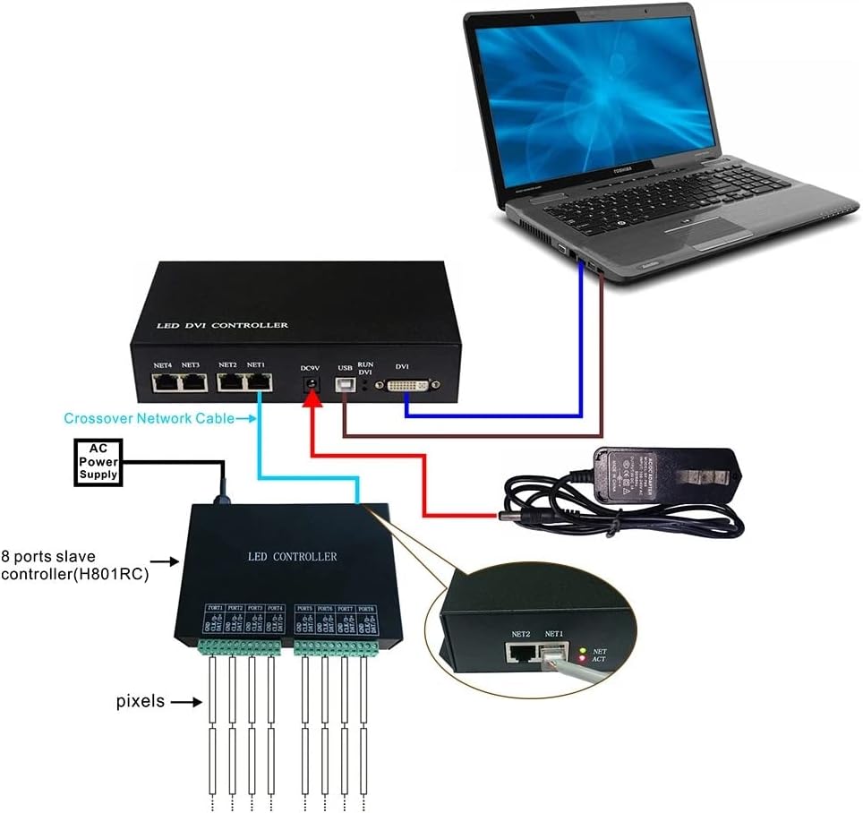
Image: A diagram illustrating the connection of the H803TV controller to a laptop via USB and DVI, and to an H801RC slave controller via a crossover network cable. The slave controller then connects to LED pixels. A DC 9V power supply is also shown connected to the H803TV.
5.2 Connecting Multiple H803TVs
For larger installations, multiple H803TV controllers can be used with a DVI distributor to expand the display area.

Image: A connection diagram showing a computer connected to a DVI distributor, which then feeds DVI signals to multiple H803TV controllers. Each H803TV controller then connects to its respective slave controllers and LED displays.
6. Operation Instructions
6.1 Initial Setup and Driver Installation
- After powering on, connect the computer's USB interface to the H803TV USB port using the provided USB cable.
- Connect the computer's DVI or HDMI interface to the H803TV DVI port using the DVI cable. The computer should automatically detect the device.
- Neither 32-bit nor 64-bit operating systems require a separate USB driver installation.
6.2 Configuring Display Mode (Windows)
- Right-click on the desktop and open the "NVIDIA control panel" (or equivalent display settings for other graphics cards).
- Select "set up multiple monitors".
- Choose "duplication mode".
- Click "apply". The DVI indicator light on the H803TV will illuminate, confirming correct DVI communication. This mode is recommended for compatibility with two monitors.
6.3 Using LED Studio Software
- In "LED Studio Software", navigate to the menu and click "setting" -> "system setting" -> "Software Setting" -> "Hardware interface".
- Select "H803TV-DVI" and click "OK".
- Restart the software for changes to take effect.
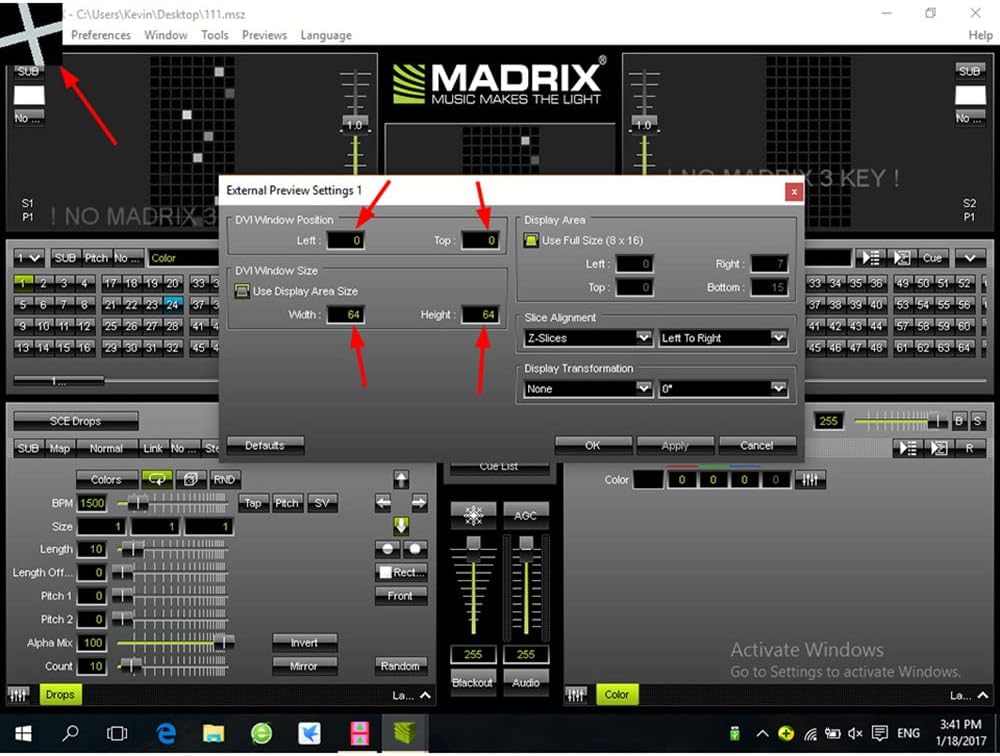
Image: A screenshot of the LED Studio software. It shows options for choosing connection mode (Single Row, Single Col, Return Row, Return Col, Shor distance, Short dist row), setting the module type (Single pixel), and defining the LineLimitPixels (e.g., 512) to limit the pixel number of each port. A grid representing the LED display is visible, with numbered ports and their pixel counts.
6.4 Pixel Control and Slave Controllers
- Each H803TV drives a maximum of 400,000 pixels with four network output ports. Each network port can drive a maximum of 100,000 pixels and connect to a maximum of 255 slave controllers.
- The more pixels each slave controller drives, the fewer slave controllers each network port of the H803TV can control.
- The H803TV can directly output to H803TC for online or offline functions.
- To connect the H803TV to a photoelectric converter via an IP switch for prolonged distance, connect the slave controller accordingly.
6.5 Indicator Lights
- Red light: Power is on. Flash indicates DVI communication is correct.
- Green light: Off indicates no sculpt load. Flash indicates the controller is working normally.
6.6 Important Note on USB Cable
Only when setting the system or sculpting the display does the computer need to send configuration data to the H803TV via the USB interface. After setting the parameters, the USB cable can be unplugged. Do not move the playing window. If no special needs, click menu "setting" -> "play window setting" -> "lock play window" in the software.
7. Troubleshooting
This section provides solutions to common issues you might encounter.
- No DVI indicator light: Ensure the DVI cable is securely connected and the computer's display settings are configured for "duplication mode" as described in Section 6.2.
- Green light off: This indicates no sculpt load. Verify that the slave controllers are properly connected and configured, and that the LED display is receiving data.
- Controller not working normally (Green light flashing): If the green light is flashing, the controller is working normally. If issues persist, check all cable connections and software settings.
- Display issues (e.g., incorrect colors, flickering):
- Verify the correct chip type is selected in the LED Studio software (refer to Section 4 for supported chips).
- Check the "Slave setting" parameters in the software, including Brightness, Clock Rate, Port Number, and Gamma.
- Ensure the screen refresh frequency is set to 60Hz (refer to Section 3.1).

Image: A screenshot of the Jinx! LED Matrix Control software, highlighting the "Configure DVI Window" option under the "Setup" menu. This interface is used for advanced DVI output configuration.

Image: A screenshot of the Madrix software, displaying an "External Preview Settings 1" dialog box. This dialog allows configuration of DVI window position, size (width and height), display area, and slice alignment for external display output.

Image: A screenshot of the "Slave setting" interface within the LED control software. It shows adjustable parameters such as Brightness, Clock Rate, Port Number, Gamma, and options for LightType, ControlType, and individual port settings for Red, Green, and Blue values. Network ports 1-4 are indicated with red arrows pointing to the corresponding settings in the table.
8. Compliance Information
8.1 FCC Statement
This device complies with part 15 of the FCC Rules. Operation is subject to the following two conditions:
- This device may not cause harmful interference.
- This device must accept any interference received, including interference that may cause undesired operation.

Image: A document showing manufacturer details (SHENZHEN HENGTU LIGHTING ENGINEERING CO., LTD), address, FCC compliance statement, manufacturer email, and EU/UK authorized representative information. It also includes a warning about plastic bag suffocation.