QIWO QW80BL007-650
QIWO QW80BL007-650 BLDC Motor and Driver Kit Instruction Manual
Model: QW80BL007-650 | Brand: QIWO
1. Introduction
This manual provides detailed instructions for the safe and efficient operation, installation, and maintenance of your QIWO QW80BL007-650 Brushless DC (BLDC) Motor and Driver Kit. Please read this manual thoroughly before installation and operation to ensure proper usage and to prevent damage to the equipment or injury to personnel.
The QIWO QW80BL007-650 kit includes a high-performance 650W BLDC motor and a compatible driver, designed for various industrial and precision control applications. This kit offers reliable operation with features such as Hall position sensing, external speed regulation, and comprehensive protection mechanisms.
2. Safety Instructions
WARNING: Failure to follow these safety instructions may result in electric shock, fire, serious injury, or death.
- Always disconnect power before performing any installation, wiring, or maintenance procedures.
- Ensure that all electrical connections are made by a qualified electrician and comply with local and national electrical codes.
- Verify the input voltage matches the specifications of the driver (110-130VDC or 220-240VDC). Incorrect voltage can cause severe damage.
- Do not operate the motor or driver in wet or damp conditions, or in environments with flammable gases or liquids.
- Keep hands and loose clothing away from moving parts of the motor during operation.
- Ensure proper grounding of the equipment to prevent electrical hazards.
- Do not attempt to disassemble or modify the motor or driver. Refer all servicing to qualified personnel.
- The motor may become hot during operation. Avoid direct contact to prevent burns.
3. Product Overview
The QIWO QW80BL007-650 BLDC Motor and Driver Kit consists of a brushless DC motor and a dedicated driver unit. The motor is an 80mm square flange design, offering 650W of power with rated speeds of 3000 RPM or 6000 RPM, depending on the specific model variant. The driver provides precise control over motor speed and direction, incorporating various protection features.
3.1 Components Included
- QIWO QW80BL007-650 BLDC Motor
- QIWO BLDC Motor Driver (Model: QW-HV-01BL)
3.2 Visual Representation of Components

Figure 3.2.1: The QIWO QW80BL007-650 BLDC Motor and its corresponding driver unit. The driver features control buttons, a speed regulation knob, and a digital display.
4. Specifications
4.1 Motor Parameters (Model: QW80BL007-650)
- Rated Power: 650W
- Input Voltage: 110-130VDC or 220-240VDC (depending on variant)
- Rated Speed: 3000 RPM or 6000 RPM (depending on variant)
- Holding Torque: 2.07 N.m (for 3000 RPM) / 1.03 N.m (for 6000 RPM)
- Flange Size: 80mm
- Output Shaft Diameter: 14 MM
- Number of Poles: 6
4.2 Driver Functions
- Hall position sensor adoption
- External potentiometer stepless speed regulation interface
- External analog speed control capability
- Six-digit display speed panel
- Power supply: 220-240V or 110-130V (AC input for driver)
- External positive and reverse selection switch connection
- Built-in thermal protection
- Over current protection
- Hall error protection
4.3 Dimensional Drawings

Figure 4.3.1: Technical drawing of the BLDC motor, showing overall dimensions including length, shaft diameter, and mounting hole positions. All dimensions are in millimeters (mm).
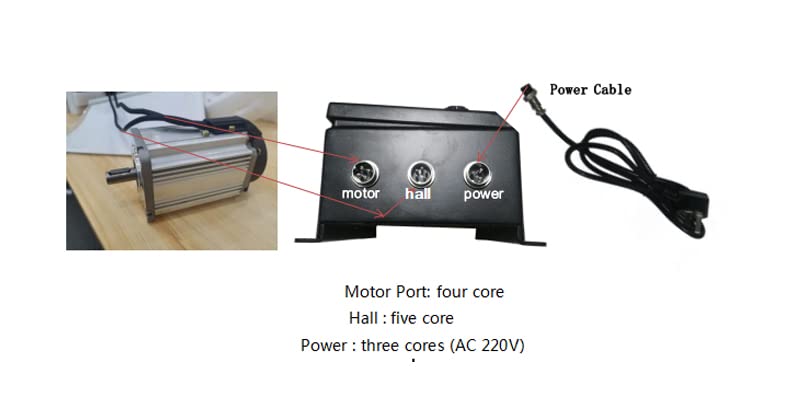
Figure 4.3.2: Technical drawing of the BLDC motor driver, illustrating its physical dimensions for mounting and integration. All dimensions are in millimeters (mm).
4.4 Detailed Parameter Table for QW80BL007 Series

Figure 4.4.1: Comprehensive parameter table for various QW80BL007 series BLDC motors, including rated power, speed, torque, and physical dimensions. Locate the row corresponding to your specific model (e.g., QW80BL007 30-650 or 60-650) for precise specifications.
5. Setup and Installation
Careful installation is crucial for the optimal performance and longevity of the motor and driver kit. Follow these steps for proper setup.
5.1 Mounting the Motor
- Mount the motor securely using appropriate fasteners through the flange mounting holes. Refer to Figure 4.3.1 for mounting dimensions.
- Ensure the mounting surface is flat and rigid to prevent vibration.
- Allow adequate space around the motor for ventilation and heat dissipation.
5.2 Mounting the Driver
- Mount the driver in a clean, dry, and well-ventilated area.
- Use appropriate screws to secure the driver to a stable surface. Refer to Figure 4.3.2 for driver mounting dimensions.
- Avoid mounting the driver near sources of strong electromagnetic interference or excessive heat.
5.3 Wiring Connections
Before making any connections, ensure the main power supply is OFF.
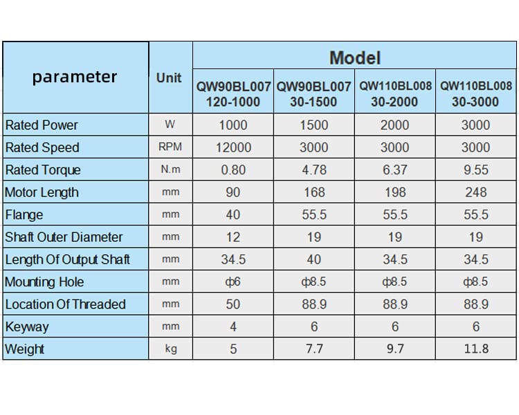
Figure 5.3.1: Diagram illustrating the connection ports on the BLDC motor driver: Motor Port (four core), Hall Port (five core), and Power Port (three core for AC 220V or 110V input).
- Motor Connection: Connect the motor's power wires to the "Motor Port" on the driver. This is typically a four-core connection. Ensure correct phase sequence for proper rotation.
- Hall Sensor Connection: Connect the motor's Hall sensor wires to the "Hall Port" on the driver. This is typically a five-core connection. Incorrect Hall sensor wiring will prevent the motor from operating correctly.
- Power Supply Connection: Connect the AC power supply (110V or 220V, depending on your driver variant) to the "Power Port" on the driver. This is a three-core connection (Live, Neutral, Ground). Ensure proper grounding.
- External Control Connections (Optional):
- Speed Regulation: If using an external potentiometer or analog signal for speed control, connect it to the designated terminals on the driver. The built-in knob can also be used.
- Direction Control: If using an external switch for forward/reverse control, connect it to the designated terminals.
Double-check all wiring connections before applying power to prevent damage to the motor or driver.
6. Operation
Once the motor and driver are correctly installed and wired, you can proceed with operation.
6.1 Initial Power-Up
- Ensure all connections are secure and correct.
- Turn on the main power supply to the driver.
- The digital display on the driver should illuminate, indicating power.
6.2 Basic Controls
- Power Switch: Located on the driver, this switch controls the main power to the driver unit.
- Run/Stop Button: Press this button to start or stop the motor.
- FWD/REV Button: Press this button to toggle the motor's direction of rotation (Forward/Reverse).
- Speed Regulation Knob: Rotate this knob to adjust the motor's speed. Turning clockwise typically increases speed, while counter-clockwise decreases it.
- Digital Display: Shows the current operating speed of the motor (typically in RPM or a scaled value).
6.3 Speed Control
The driver supports both internal potentiometer (knob) and external analog signal for speed control. If an external signal is connected, the internal knob may be overridden or used for fine-tuning, depending on the driver's configuration.
6.4 Direction Control
The motor direction can be changed using the FWD/REV button on the driver or via an external switch connected to the designated terminals.
7. Maintenance
Regular maintenance ensures the longevity and reliable performance of your QIWO BLDC motor and driver kit.
- Cleaning: Keep the motor and driver free from dust, dirt, and debris. Use a soft, dry cloth for cleaning. Do not use solvents or abrasive cleaners.
- Ventilation: Ensure that the ventilation openings on the motor and driver are not obstructed to prevent overheating.
- Connections: Periodically check all electrical connections for tightness and signs of wear or corrosion. Tighten any loose connections.
- Environmental Conditions: Operate the equipment within its specified temperature and humidity ranges.
- Inspection: Visually inspect the motor for any signs of damage, unusual wear, or excessive vibration during operation.
WARNING: Always disconnect power before performing any maintenance or inspection.
8. Troubleshooting
This section provides solutions to common issues you might encounter. If the problem persists, contact technical support.
| Problem | Possible Cause | Solution |
|---|---|---|
| Motor does not start |
|
|
| Motor runs erratically or vibrates excessively |
|
|
| Motor does not reach desired speed |
|
|
| Driver display shows an error code |
|
|
9. Warranty and Support
For warranty information, please refer to the terms and conditions provided at the point of purchase or contact your vendor. QIWO products are designed for reliability and performance, and technical support is available for assistance with installation, operation, and troubleshooting.
For technical assistance or inquiries, please contact QIWO customer service through the retailer or official QIWO channels.
Ask a question about this manual
Ask about setup, troubleshooting, compatibility, parts, safety, or missing instructions. Manuals+ will review the question and use this page’s manual context to help answer it.